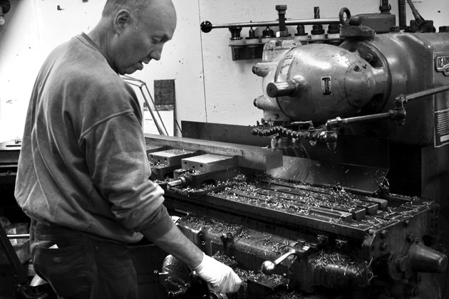
From May 14, 2018 to August 10, 2018 I interned at Paragon Machine Works, a machine shop in Richmond, CA. Paragon’s primary business is that of making parts for hand-built bicycle frame builders. Anything (and everything) that is too complicated to be manufactured by the frame builder is made by Paragon. These parts include those that are required to be held at a specific tolerance, such as head tubes and bottom bracket shells, and parts that have complicated geometry in three (or more) axes, such as dropouts and cable stops.
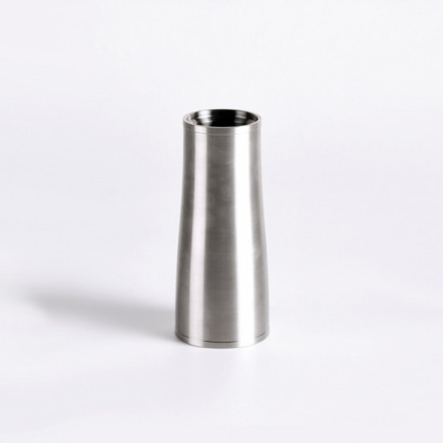
I was hired with one primary and overarching goal. This goal relates Computer Aided Design (CAD) to Computer Aided Machining (CAM). In my experience and what I believe to be the experience of most, CAD software is a separate entity from CAM software. This means that in the design process, a solid is constructed from a sketch in a CAD program, and that solid is analyzed in a separate CAM program to produce machine instructions. This relates to my hiring because Mark Norstad, the owner and founder of Paragon Machine Works, currently makes titanium headtubes that support IS 44/47 and IS 44/52 bearing sizes in a number of fixed lengths. The geometry of these head tubes is such that the majority of the outer and inner profile are defined by two tangent arcs whose radii are defined by the overall length of the head tube. A figure is shown below to better illustrate the geometry. This means that each length of each of these head tubes required a separate CAD file and CAM file from the rest. (Nomenclature becomes a bit misleading here, so keep in mind that a ‘CAD file’ and a ‘CAM file’ are more like individually tailored CAD and CAM programs than just ‘files’). Clearly the creation of a new length head tube, let alone line of products with a different bearing dimension, is extremely labor intensive and likely not cost effective with this system. Here is where I come in.
The goal is to have CAD/CAM associativity. This means that we want to have one CAD file whose principal dimension is the length of the head tube, and we want to be able to vary that length and have resulting tangential arcs and useable machine instructions readily follow that length modification. Much, much, much easier said than done.
Paragon has used and continues to use Solidworks as their main CAD software. Solidworks is a very powerful piece of software and I am both trained in its use and a fan of using it. However, I am told that its CAD/CAM associativity has a high cost barrier to entry which is not worthwhile for a small business like Paragon. This led us to try Autodesk’s Fusion360 for its ease of associativity. Fusion360’s CAD and CAM are a part of the same program, so it is natural and even somewhat intuitive to use them together. I drew the sketches and made the solids of the headtubes we wanted to produce and began to work on the CAM.
There is an interesting dynamic in the world of manufacturing and it exists because that world is so large and so complex. Those people who are in the business of physically producing parts and products are typically not the same people that write the software that enable others to produce those parts and products, and the same is true when the roles are reversed. This is to say that a machinist at Paragon Machine Works is not likely to go on and produce the next Fusion360. This is also to say that the programmers working on Fusion360 are not likely to work as machinists in their lifetime. This becomes an interesting facet of this world when you realize that the programmer is now supposed to make a product that helps an end user accomplish something that the programmer has no (or next to no) experience in: machine parts in a production environment.
So this is what we’re left with in most cases: the programmer hasn’t made software that captures the desires of the machinist, and the machinist can’t program their way out of their situation. Autodesk tries the hardest that I have seen to take into consideration the concerns of machinists that use their products. They do this by monitoring and participating in online forums accessed from their website. They update every month or so and try to incorporate users’ concerns in their update.
This is the case to a certain point. It seems as though they have chosen to use their time to add new (and often niche) features rather than solidify and strengthen their basic features. They seem to be captivated by adding features for as many axes as they can while not realizing that an enormous amount of production (likely an overwhelming majority) occurs on 2 and 3 axis machines.

I frequented the Fusion360 CAM forums in my tenure as intern at Paragon. Even though we were working on a 2-axis lathe, there were still a great many issues with the way Fusion360 wanted to have things done. The CAM forum community is very helpful and very instructive. I would feel bad if I didn’t give Neal Stein and Lonnie Cady mention for their particularly helpful advice and vast knowledge. They and others helped solve my issues and send me in the right direction towards an effective program.
Once we had gotten far enough in Fusion360 that the program was on the same page operations-wise as we were in the shop, it came time to create a post-processor that read the CAM file specifically for the machines we would produce these products on. Simply, a post-processor is a 1300-1400-line program written in Javascript that interprets the location and work coordinate data from the CAM file, assesses the geometry of the tools to be used and the order of tooling, and then uses this information to write machine instructions. Machines operate on a very simple numerical control language called G-Code. G-Code was created by researchers at MIT for use on CNC machines, and as such it is very well suited to their operation. It accounts for things like work coordinates, coolant, feed rates, and any other possible machine operation you could imagine. As all machines are different from one another, it is crucial that the proper G-Code is written for each machine. Things like choosing flood coolant vs. high pressure coolant, or an improper work coordinate callout sound simple, but in reality, can cause expensive crashes and other problems. This means that there must be a post-processor written for each machine so that it can output the correct code that requires minimal editing before being put into the machine.
I ultimately wrote three post-processors for Paragon Machine Works, one for our Okuma and Howa ACT-20, one for our Nakamura-Tome SC-250 and one for our EMCO turning center. In reality, I wrote three for each of these machines before finalizing them for production use. They contain the correct coolant codes (much more logic driven and complicated than they sound), safe tool change positions, and the correct ending sequences for how we do our production.
With these post-processors out of the way, I finally had a fully associative CAD/CAM program that would produce code that is useable for production in under 5 minutes. This was a formidable accomplishment and something that Paragon had never had before. Prior to this program, it would take them somewhere in the neighborhood of 5 concentrated hours to produce a different headtube of this nature. We began production of a new style of headtube and they are now available for sale. They can be found here.

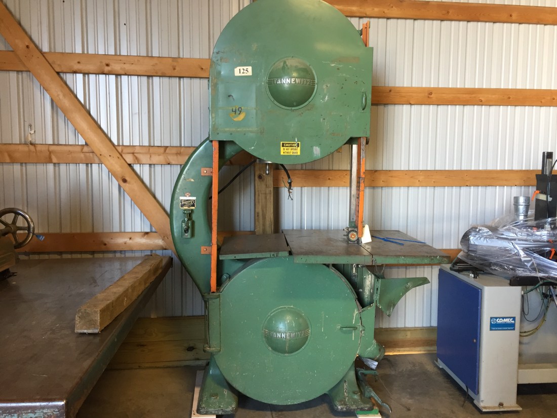
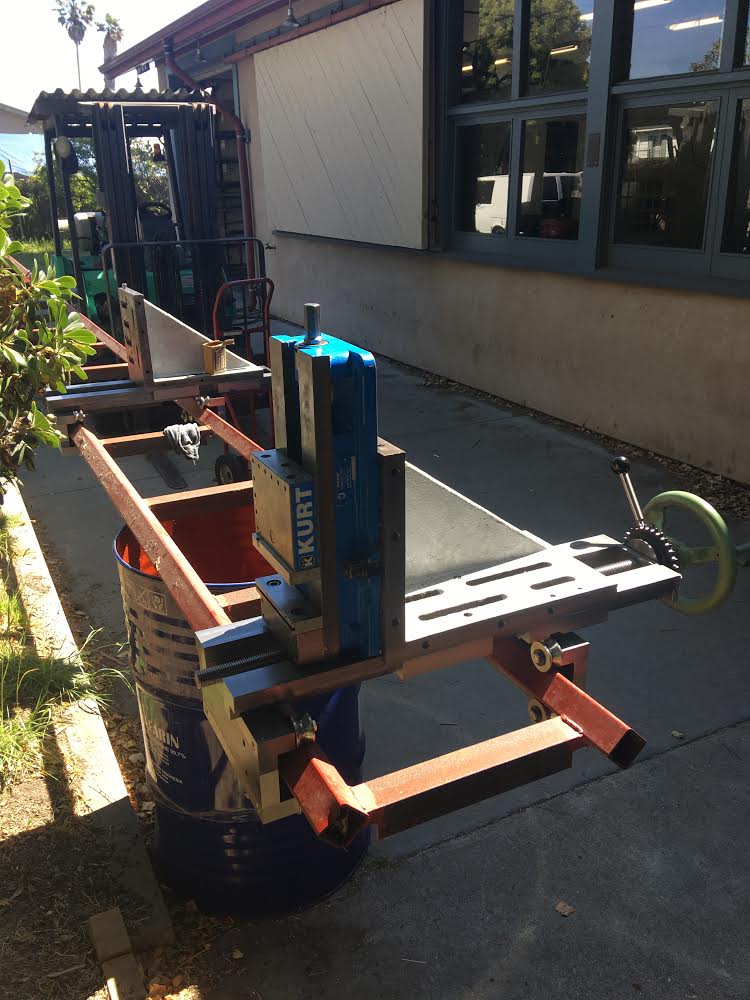
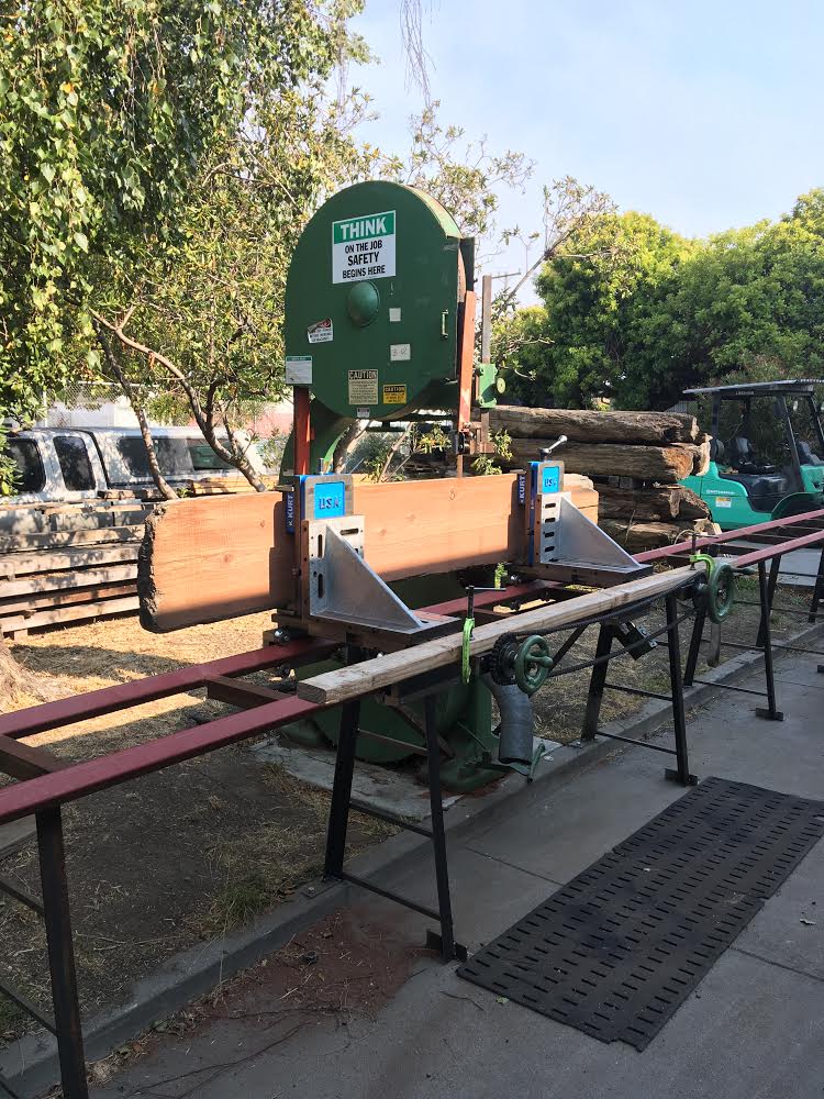
The head tube project occupied about half of my time at Paragon. The other half was spent designing, programming, machining, assembling, and fabricating a saw mill carriage for our pre-war 36” Tannewitz band saw. Mark began this project some five years ago when he acquired the saw which is a truly massive and impressive piece of machinery. Even after sitting outside for five years, the two solid iron 36” wheels are able to be turned at once by two fingers on the blade – a sign of unparalleled quality and reliability in my opinion. Mark made some new guides for the blade and begun drawings for how he imagined the mill would work. He made a fixture and welded a 30-foot-long set of rails on which the future mill would slide, and then set the project aside for a while.
He wanted the ability to control both carriages’ distance from the blade (X-axis) so that it truly was a saw mill. To move each carriage, we used an 8TPI ACME threaded rod controlled by an original Tannewitz handwheel. The reason for the 8TPI was that woodworking is most often done in fractional inch increments, so this would allow us to saw to those increments quite easily with identifiable fractional turn increments of the handwheel. This means that one turn of the handwheel moves the mill 1/8” in the X-axis and so on. To move the carriages fore and aft in unison, we attached a roller chain sprocket to each carriage and ran a #40 roller chain between them. This way, when one handwheel was turned, the other would turn as well. However, because there might come a time when we want the chain to remain tensioned but move one of the carriages independent of the other, we added a clutch system. When released, the clutch system would allow the two handwheels to spin independently, and when tightened would have them move in together.
Mark had me look at his drawings (which were written in an archaic piece of software called Powerstation) and then we sat down and discussed what we thought the design of the carriages would be. I got to prototyping in Solidworks and ended up spending the next three weeks or so creating and refining the designs of all of the various pieces to be involved. The goals were versatility and minimalism. We wanted to be able to arrange the components of the system in as many ways as we could to be able to accommodate the largest number of possible configurations of stock. We also wanted to have the system be simple and robust enough to sit outside year-round and still function properly.
To accommodate these parameters and ensure that it worked properly before we started machining, I made a Solidworks model of every part and put them all into one enormous assembly with more than 35 components. I had to ensure that every screw hole lined up properly, that every counterbore was the right depth, that every dowel pin hole was lined up, and that as many pieces as possible were interchangeable with others. I had to ensure that the carriage would actually sit on the rails that had already been produced, and that there would be no interferences. Once all of this was done and we liked how the design functioned, it became time to start making machine instructions for the pieces we wanted to make. I imported every file into MasterCAM and started making CAM files for each part. This was extremely time consuming but was crucial to avoiding crashes once in the machine. Each file was proofread at least three times, and each file was edited to match our specific machines.
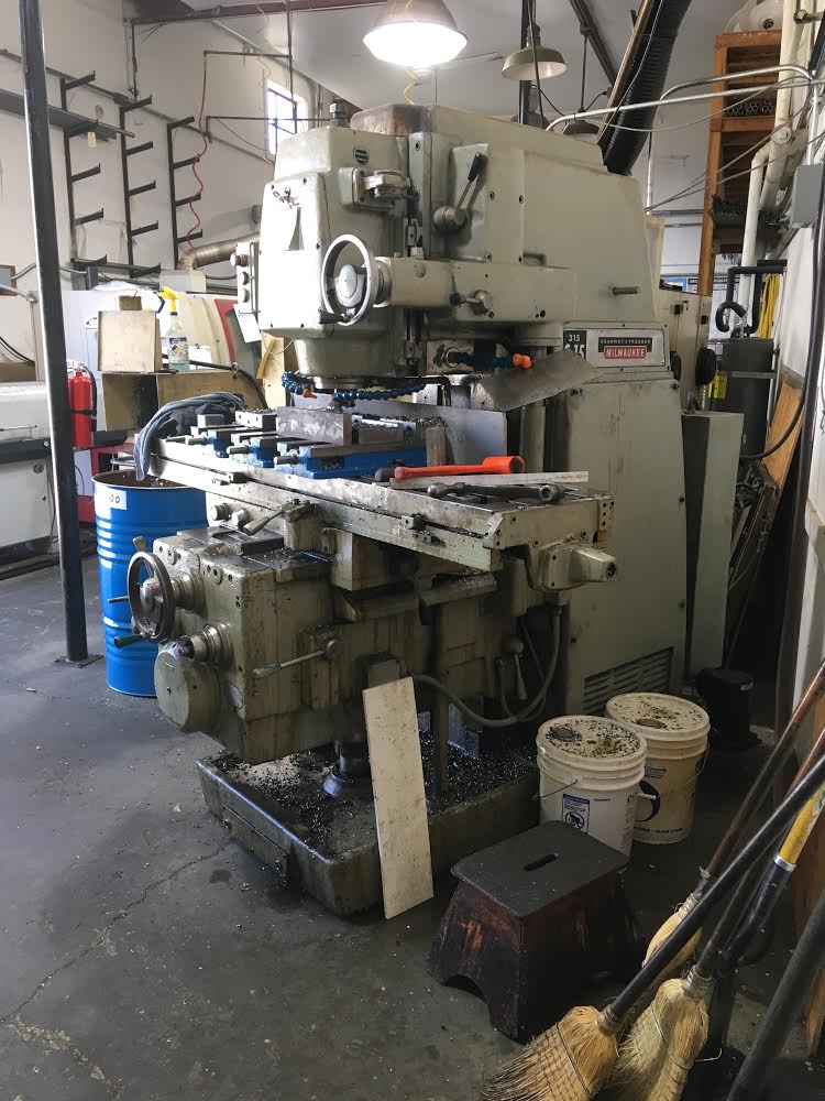
All of the stock that was to be machined required preparation before it was able to be put in a machine. Generally, pieces were cut to length on a Do-All bandsaw and faced on a Kearney and Trecker S-15. If you haven’t had the privilege of seeing or working on an S-315, I highly recommend changing that because it is an amazing and enormous machine. I was able to bury the inserts on a 4.5” face mill completely to their limit of cutting and the machine did not bat an eye. That’s nearly a .350” depth of cut on mild steel. Amazing. Some of the steel we used was cut from a retired forklift blade. Fork lift blades are made from the same steel as railroad tracks, which work harden due to the fact that the alloy is high in manganese. This means that machining these forklift blades must be done much more carefully and much slower to avoid breaking tools. Still the K&T prevailed. All said and done I must’ve spent some 60 hours just cutting and facing the stock to be put in the CNC mill.
The majority of our machining work to be done was some variation of a hole being drilled. However, to make something as simple as a dowel pin hole, there are three separate drilling operations that need to be performed:
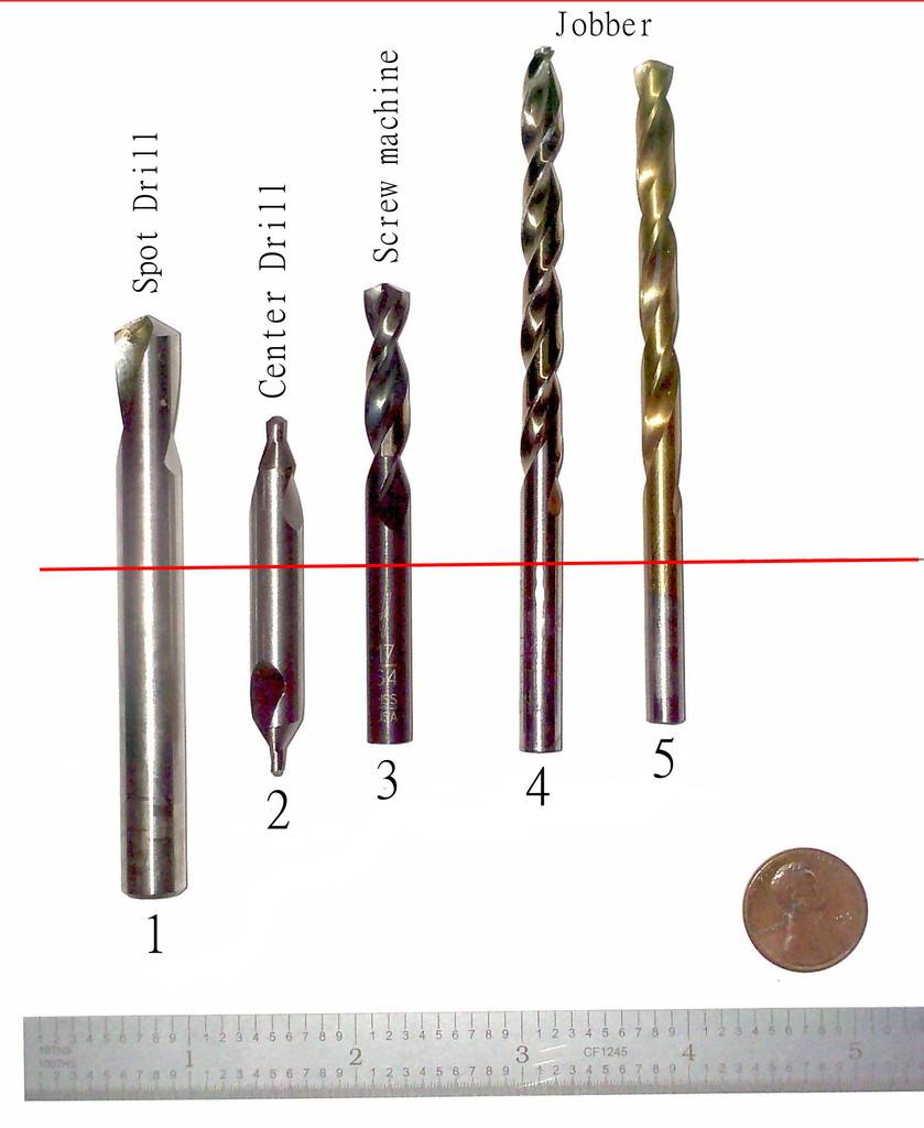
As a rule, every hole that is to be drilled first requires a spot drill. A spot drill is a screw machine length drill (read: short) that has a 90 degree point rather than the typical 135 or 118-degree points on common drills. The spot drill that we typically use is ½” in diameter. The purpose of the spot drill is to set the location of the drill that brings the hole to size. The spot drill is rigid and does not flex as much as a normal twist drill, so it is ideal for this purpose. The spot drill goes as far into the work as the radius of the desired hole. This means that a .250” hole has a spot drill depth of .125”.
After a tool change to the appropriate sized twist drill for the desired hole, the new drill is sent down to the spot drilled hole in one of two ways: a drill cycle or a peck cycle. A drill cycle sends the drill to the desired depth in one move in the -Z direction, and then returns back to a safe height above the work in one move in the +Z direction. A peck cycle has a defined “peck depth” which governs how far the drill incrementally goes before retracting to the safe height in a peck-like movement, hence the name. The purpose of the drill cycle is to quickly drill a shallow hole, and the purpose of the peck cycle is to evacuate chips created in the drilling of the hole. A drill cycle is chosen when the desired drill depth is roughly similar to the diameter of the drill, and the peck cycle is chosen when the drill depth is much deeper than the diameter of the drill. For our dowel pin hole, a drill cycle would be chosen because our desired drill depth is .400” and the diameter of our drill is .238” (in this case we are using a letter B drill).
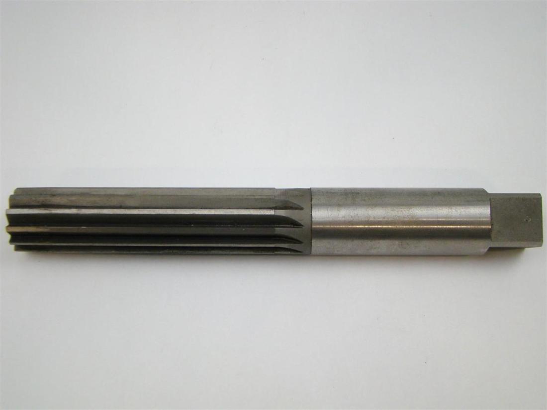
After our hole is drilled to .400” deep, we must change tools to a reamer. A reamer takes an undersized hole that has already been drilled and brings it to a very specific and accurate diameter. In a typical dowel pin configuration, there is one hole reamed to .001” undersize and one hole reamed to .001” oversize. This allows for one side to be pressed in and for the other to have a location fit. In this case, we are using a .249” reamer for our .250” dowel pin. On the other side we will use a .251” reamer so we can have our location fit. The reamer is sent in a drill cycle with a very slow spindle speed and a very fast feed rate to a depth .1” above the maximum drill depth of the existing hole, which in this case would be .300” deep. This is to allow for adequate clearance for chips as the reamer cuts the stock.
Now we have our one dowel pin hole. Each of the two carriages that I made has 42 dowel pin holes. We haven’t even begun drilling and tapping, counterboring, pocketing, and facing. All of these operations are performed in some way shape or form on every piece, and most of the time on four or more sides of the same piece. Four of our pieces were 30” long and required clever ways of getting around our maximum X-axis travel of the same 30”.
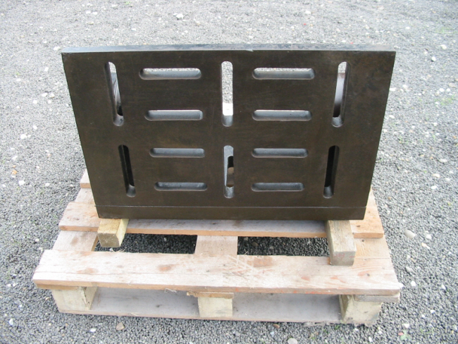
The principal component of each carriage is the cast iron angle plate. These angle plates, or knees, were in reality one much larger knee prior to my hiring at Paragon. We cut the original knee into two equal sized knees and faced them to an accurate width. There is work on six sides of these behemoth chunks of metal, and we had no shortage of headaches trying to be able to machine all of them, even in our largest CNC mill. We had to pull our ~600lb vise table off of the mill’s table with an engine hoist, and clamp each knee directly to the table just to be able to perform all of our work. We had to indicate off of a surface we could only hope was true. We had to include a move to a safe location before every single tool change because the knees were so large that they would otherwise get hit by the tool changer. We had to clamp one knee to the other to work on the faces because we had no other way of holding them upright. This meant that at the maximum we worked on stock that was an enormous thirty-two inches long! We truly made use of all of the available space in our mill by working on stock that measured 12” x 9” x 16” at an absolute minimum. Keep in mind that in this mill and all of our mills we typically work on stock that is no larger than 5” x 3” x 2.”

Finally, once the machining was done, it was time for assembly. The carriage fit together perfectly with absolutely no hiccups whatsoever, which was testament to the rigor and precision of our design work and machining.
Now that the carriages were together, it was time to fabricate a rail system that would allow them to slide parallel to the blade of the saw and level with the ground. We used our forklift to set the rails that Mark made some five years ago on some 55-gallon drums and made plumb bob measurements from there to determine the ideal location for the rails. We wanted the rails to be placed in the least restrictive location they could so that we could accommodate the largest variety of stock possible. Once our design was complete, we cut material, drilled into the concrete, and welded our rails into place.
In my final week at Paragon Machine Works we were able to saw wood with our saw. We resawed a 12”x14”x8’ piece of reclaimed redwood and the cut was true. It was immensely satisfying to see the carriages work and work properly to give a quality cut.
I truly enjoyed my time at Paragon Machine Works. I feel that I gained an immense amount of knowledge and practical skills that I would not have otherwise been exposed to. I learned about how to manage and plan a large and complicated project and I learned how to proceed with something that I do not know how to do or have never done before. These are clearly lifelong skills that one never truly learns completely, but I feel like I have a head start on them because of my time at Paragon. My experience with projects like these will help me in my research at school and help me advance my career. I cannot give enough appreciation and thanks to Mark because I would not have learned these skills without the guidance of a true master of them. This work experience has left me with more than I could have hoped for and was something that I am very satisfied by. I give an innumerable thanks to Mark Norstad and the employees of Paragon Machine Works for this enriching experience.

One thought on “Internship at Paragon Machine Works”