I built myself a new mountain bike and I am going to explain the process and motivation. The impetus for this bike was threefold: I wanted to 1. experience what a bike with a long front center feels like, 2. use my own knowledge, design thinking, and mathematical reasoning to take a stab at optimizing a bike with a long front center, and 3. end up with something I would actually enjoy riding. Here was my process:
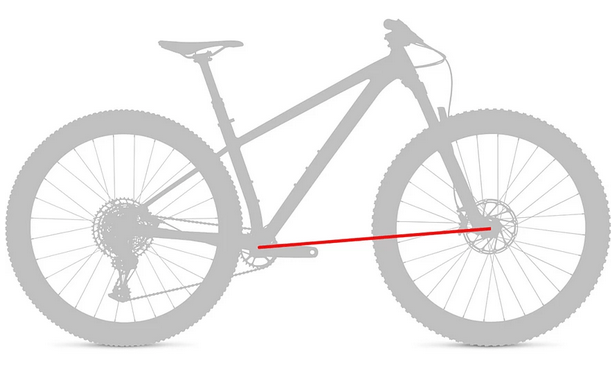
First let’s consider some terms as they relate to bicycle geometry. I’m going to design my new bike around these parameters, so it’s important that we have a solid understanding of what they are. I’ve already mentioned an important one; the front center. This is the shortest distance from the center of the bottom bracket to the center of the front axle.
In recent years, many people have focused on increasing the front center on mountain bikes. The exact physical reason for doing this isn’t very well documented or understood, but there seems to be consensus that many people enjoy riding mountain bikes with longer front centers. Some people are even willing to die on this hill.
Another important term is the normal trail. This is the line normal to the steering axis that intersects the contact patch of the front tire. It is shown below along with a derivation of the expression of normal trail. The normal trail describes the lever that the front wheel has on the handlebars. The normal trail is responsible for the caster effect, which accounts for some of the self-stability of a steerable bicycle.
The next parameter of interest is the flop height. This is the height above the ground at which the normal trail line intersects the steering axis, and it is shown below alongside a derivation for the expression of the flop height.

The flop height seems to describe the potential energy in the bicycle steering system. The system in this case is analogous to an inverted pendulum. When the wheel is straight in the perspective of the rider, the system has the maximum possible potential energy. Any deviation from this orientation results in a decrease in potential energy, which indicates that the rider must do work to restore the system to the “straight” orientation. Because the rider will never turn the handlebars more than 90 degrees in either direction from straight, (in practice this number is much lower, more like 50 degrees) a larger flop height corresponds to any angular deviation from straight causing a larger change in potential energy, which in turn requires more work to be input from the rider to keep the wheel straight.
While this may stand to reason, it is worth mentioning that there is debate about whether or not the flop height really means anything. An internet geometry cognoscente by the name of Kuromori contends that flop is essentially meaningless, and they support this proclamation with graphs and sound reasoning. Their essential argument is that flop height “gives the illusion of having some other value to optimize to counter the narrative of the optimal mid trail values” because it is a scalar multiple of normal trail, and therefore it should be ignored.
In a mathematical sense this argument is false. Flop height can be changed while holding trail constant by simultaneously changing head tube angle and fork offset, and this can be proved with easily with a graphing calculator like Desmos. This argument is also false on bikes where these two parameters are able to freely be changed, like on bikes with rigid forks. Where the argument begins to gain some traction is in the realm of mountain bikes that use suspension forks, and this is because suspension forks are typically only offered in one, two, or occasionally three different offsets. This limits the freedom of the designer and pushes reality back in the direction of Kuromori’s proposition.
This contradiction led me to wonder where to begin. What is a good flop height? What does that even mean? When set up with a 750mm OD front tire (29×2.6″ WTB Vigilante on a We Are One Insider rim) and a 51mm offset fork, the 2019 Santa Cruz Chameleon has a flop height of 35.79mm, and I like the way that it rides.
A naive way to think about this problem would be to try to build my new bike with the same or similar flop height as the old bike. This is limiting, and doesn’t consider how flop actually works. Flop height has units of mm, while the force and torque you feel at your hands have units N and N
The rider and the bike have a combined mass that contacts the ground at two locations: the contact patches of the front and rear tires. The normal force at each wheel is a function of the location of the center of mass of the rider and the bike with respect to these two contact points. This is illustrated below for clarity.
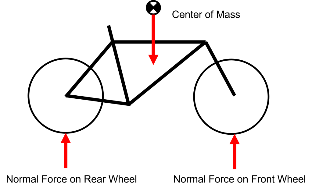
We can simplify this drawing into a free body diagram and use it to determine how the forces at each contact patch change as we move the center of mass.
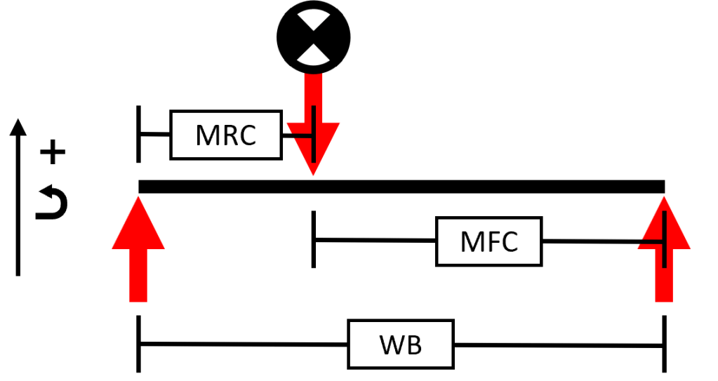
Here, “MFC” refers to what I am calling the “mass front center.” This is the horizontal distance from the center of mass to the the front contact patch. Note that due to the triangle inequality this is different from the front center of a bicycle, which I defined above. Similarly, “MRC” refers to the “mass rear center.” “WB” refers to the wheelbase of the bicycle and is the sum of MFC and MRC.
Using statics we can calculate what the forces at each wheel are. We will call the force acting at the front contact patch 


Solving these two equations we find the following expression for the force at the front contact patch:

This has some interesting implications, namely that with an increase in the distance from the center of mass to the front contact patch (and therefore the front axle), there is a decrease in the force acting on the front contact patch. Given what we’ve said above about the mechanism of flop, this implies that an increase purely in front center on a bike results in less of a flop feeling.
Flop is the most annoying and pronounced to me while climbing and at low speeds. This makes sense because the caster effect is less pronounced at low speeds. Think about trying to ride with no hands when going slow: it doesn’t work as well as at higher speeds. When I’m climbing or going slow, I’m usually sitting on the saddle, not standing. This is important because when a rider is seated, their center of mass is in a different location than when they are standing. For the following calculations I will only consider the case in which I am seated.
To measure my actual mass distribution when I am on level ground, I placed a scale under each wheel of my current bike while I was seated and simultaneously recorded the readings.
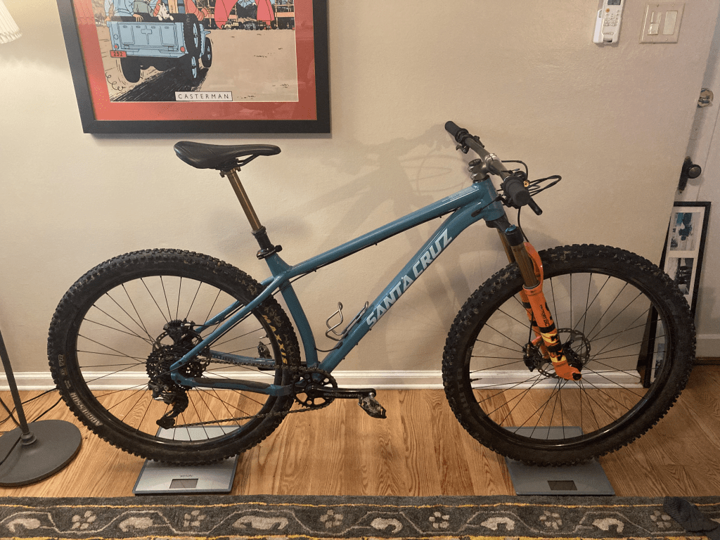
With this setup, I ended up with the following:
| Rear [kg] | Front [kg] | Rear [N] | Front [N] |
| 56.0 | 31.5 | 549.4 | 309.0 |
This is important because it tells me MRC, the horizontal distance from my COM while seated to the rear axle. My new bike will have the same rear center as the Chameleon (415mm) and a similar BB height (317mm instead of 315mm), so my MRC will be very similar on the new bike. This means I can use this known MRC and the new wheelbase to calculate the true front center for any frame design that I examine.
It makes sense to combine the force at the front contact patch and the flop height to form a stand-in for the flop feeling. This way we can do some analysis on the parameters at play in the system. Consider the following quantity, 

I have to briefly mention suspension sag here. The point of this exercise is to minimize the perceived flop feeling while seated and climbing. As sane person, I climb with my fork locked out. I take this condition to mean that I have anywhere between 0% and 15% sag at any given time climbing. For a physical bicycle the head tube angle is the slackest when the fork is the longest, i.e. 0% sag. This corresponds to the greatest flop height and therefore the greatest perceived flop (note this assumes that flop height decreases with head tube angle faster than front center does, a fact which will be proved later). This means that the worst case scenario for perceived flop is at the fork’s full extension (0% sag), so I will design for flop around that. It’ll only get better with more sag.
The variables we have control over in the expression for 
Due to my anatomy I have a set horizontal distance from the center of the saddle rail clamp to the center of the crank spindle, and a set maximum radial distance from the center of the saddle rail clamp to the hand grips. Thus, to maximize WFC I should choose the cockpit that places the hand grips at the greatest possible horizontal distance behind the steering axis (within reason for a performance mountain bike — no cruiser bars). This way WFC is as long as it can be (and by extension, the reach). Short of a custom solution I have done just that. I am using a Salsa Salt Flat bar which has a maximum offset of 54.97mm, and an Industry9 A318 stem which has a length of 31mm. This is important because for any frame configuration whatsoever, the choice of this cockpit (in combination with the hard anatomical limit of the maximum radial distance from the center of the saddle rail clamp to the center of the hand grips) offers the maximum front center for off the shelf components, no matter what. This configuration will be assumed in all of the following calculations. (Since planning this bike I have become aware of SQ labs bars that offer a larger offset. I will use SQ labs in future iterations of this bike.)
This means that the only variable over which we have control at this point is
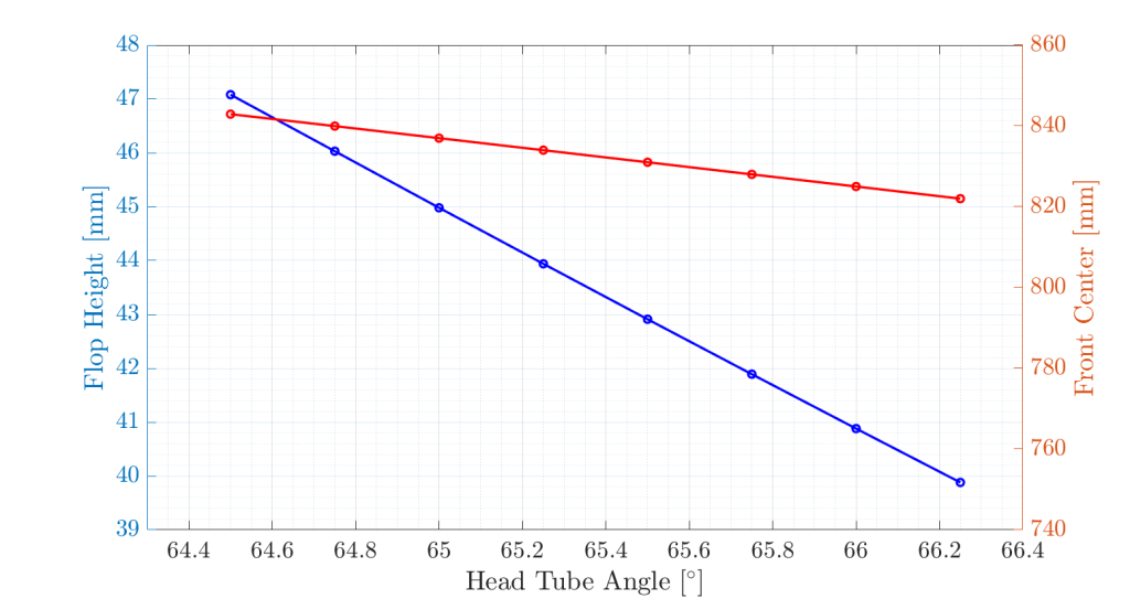 . Ignore the fact that the lines intersect on this figure as the axes are different.
This shows that, even though the expression for flop height as a function of

This means that for every addition of 1 degree to
If we fit a line to the blue curve we get the following:

This means that for every addition of 1 degree to
These lines are interesting, but they don’t tell us what we’re really looking for. What if there is some optimal configuration? To investigate this, let’s plot
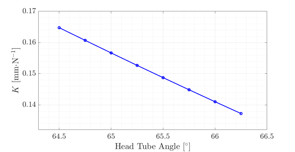
Perceived flop decreases with an increase in head tube angle. There are no hard nonlinearities and the slope is negative. Thus I am faced with a canonical engineering problem: I want to maximize front center and minimize perceived flop, but given the variables over which I have control in this system, an increase in one results in an increase of the other. As such there are no immediately apparent optima in this (simplified) space. If we examine this graph, we find that with a single degree change in
Now that the easy part is over, I have to make a design decision: which head tube angle do I choose? Any decision I make results in a compromise. I’m going to choose 65.5 degrees because it strikes a balance of front center and perceived flop that I think will satisfy my design goals for this bike. It may not, but that’s something I’ll have to find out once I ride the bike.
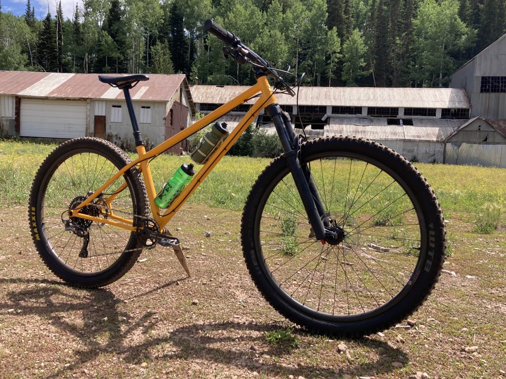
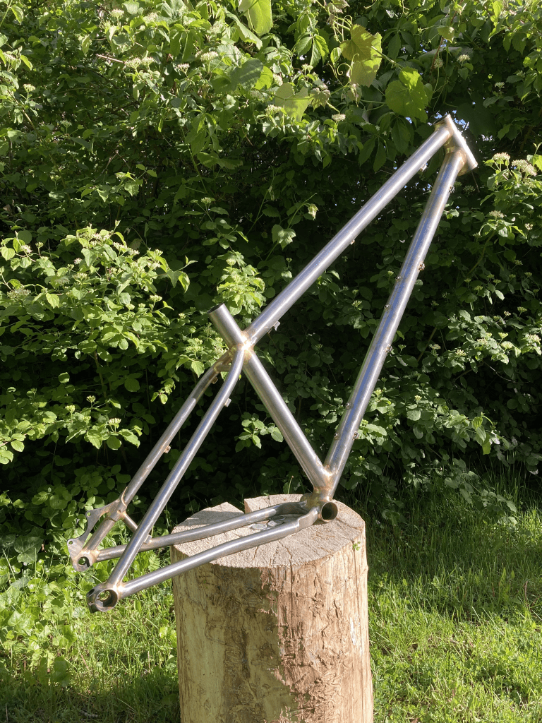
Now for the big reveal, the final drawing:

For consistency I must note that I have increased my rear center from the proposed 415mm to an actual 418mm for rear tire clearance. This 3mm change minimally affects the results of the above calculations, but it needed to be addressed.
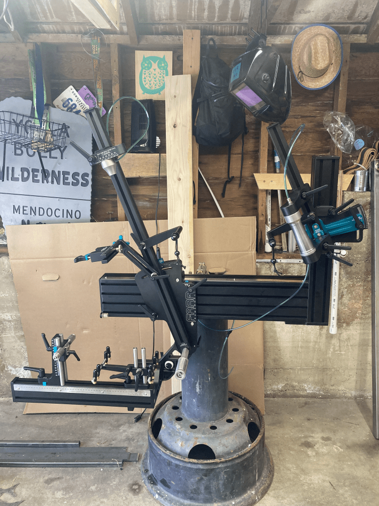
Once I had the drawing nailed down, it was time to construct the bike. This was a bike of firsts for me: the first bike to use a tapered head tube, the first bike to use additively manufactured components, the first bike with boost spacing, and the first bike to come out of my shed that’s been built on a commercial frame jig.
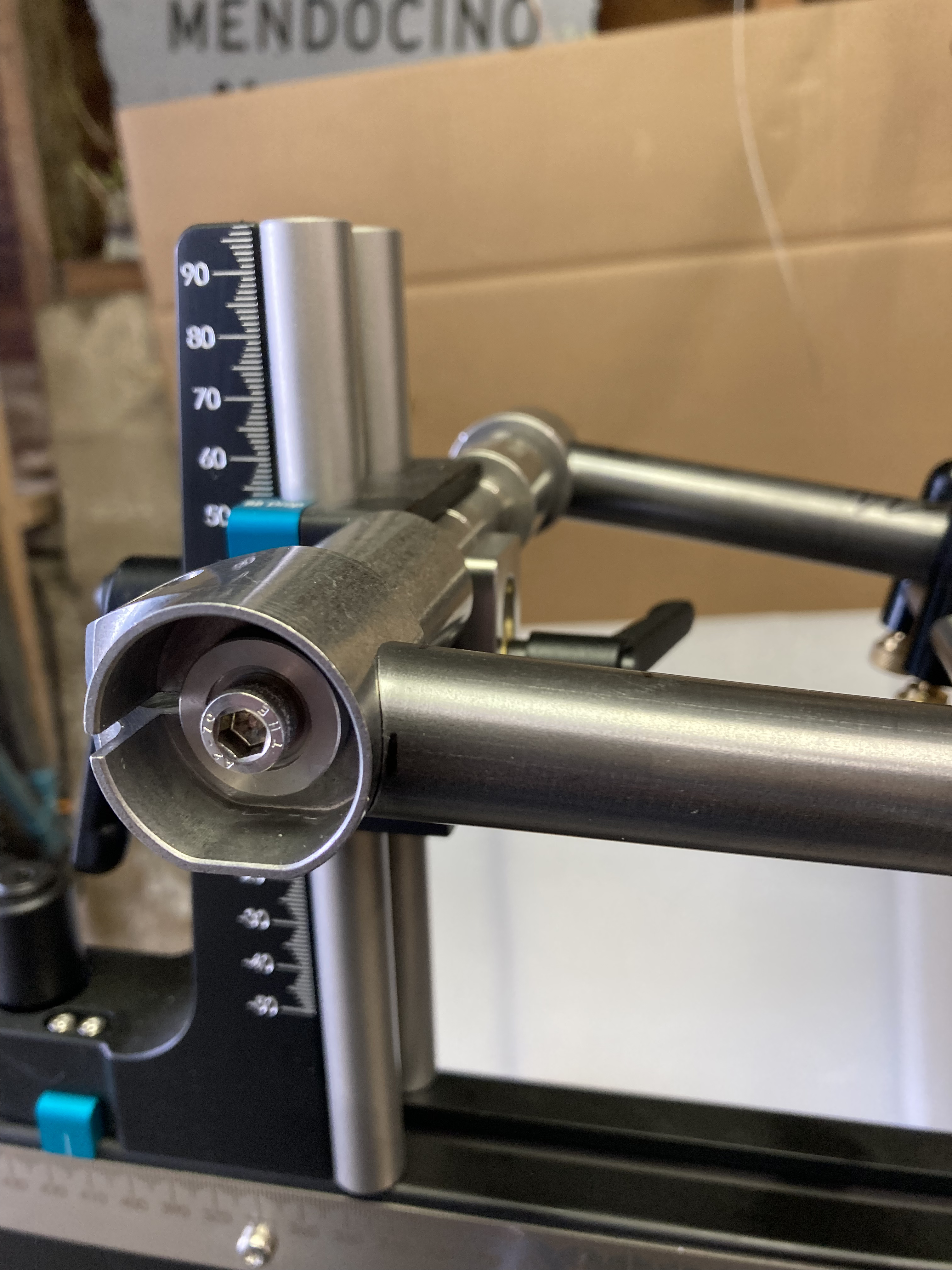
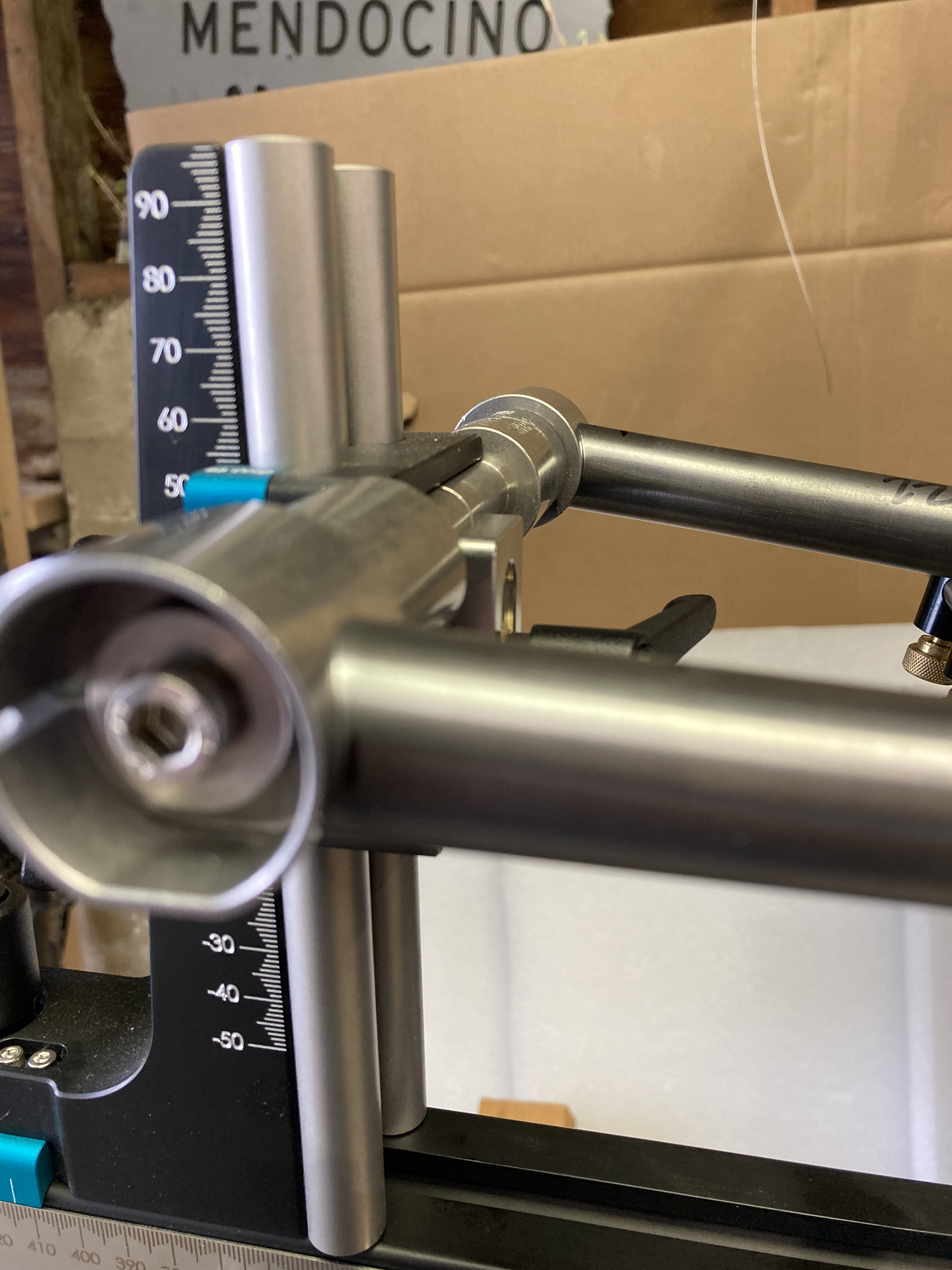
As I mentioned before, I used a Farr Frameworks BFF Jig to construct this bike. This tool has made repeatable frame construction significantly easier than it was with my home-made jig. It also has several fixtures for holding tubes in place on the frame centerline that generally make life much easier when building a bike. Thanks Todd, you did a great job with this one.
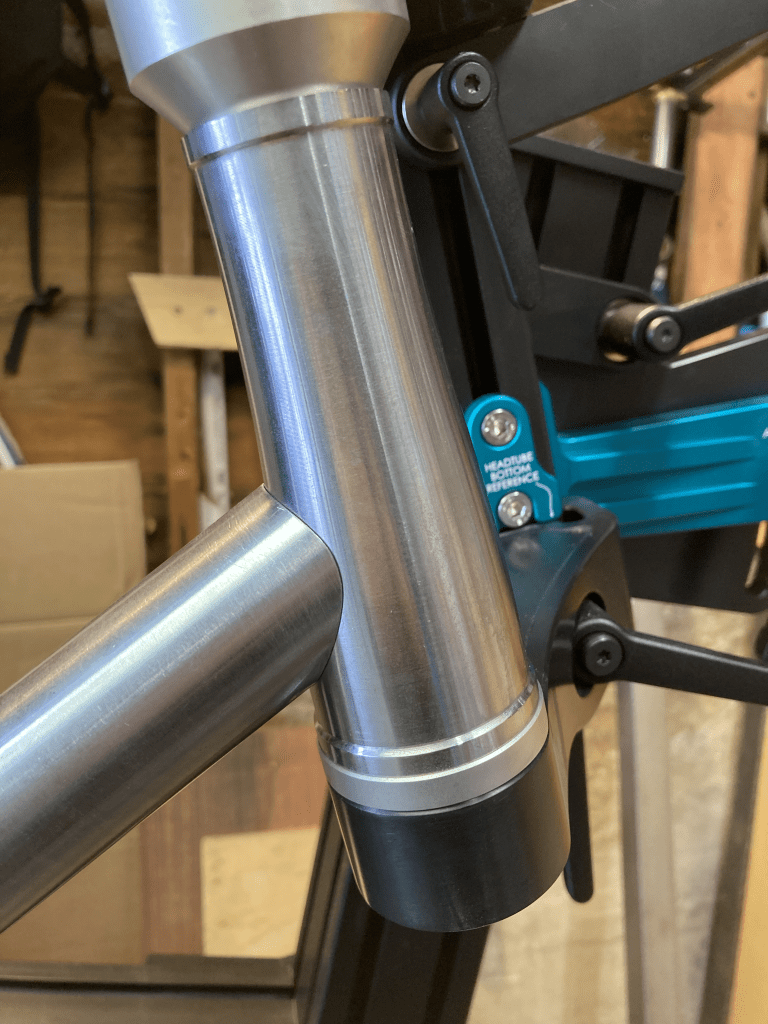
This was the first bike I have made with an externally tapered head tube. I used a Paragon Machine Works EC34-44 121mm head tube. I am proud of this because this head tube was a product that I played a large role in bringing to life when I worked at Paragon. I wrote the parametric and associative CAD and CAM for this product line, so it feels immensely satisfying to build a bike for myself with one.
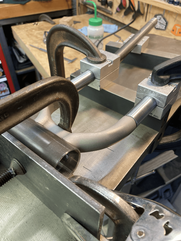
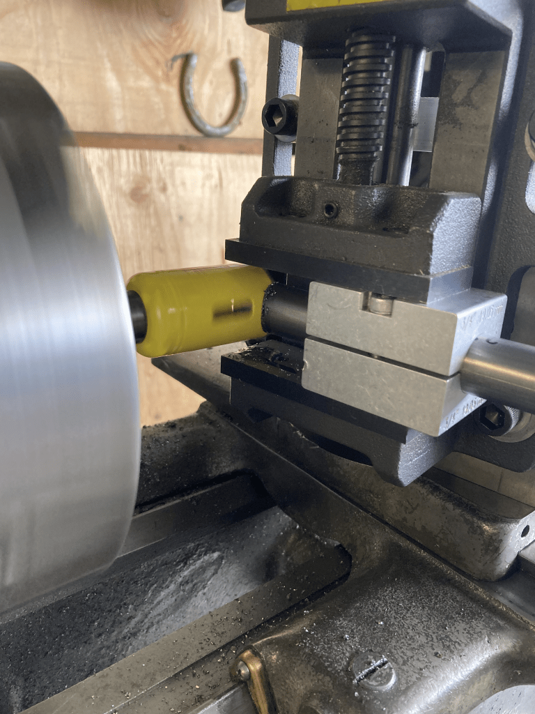
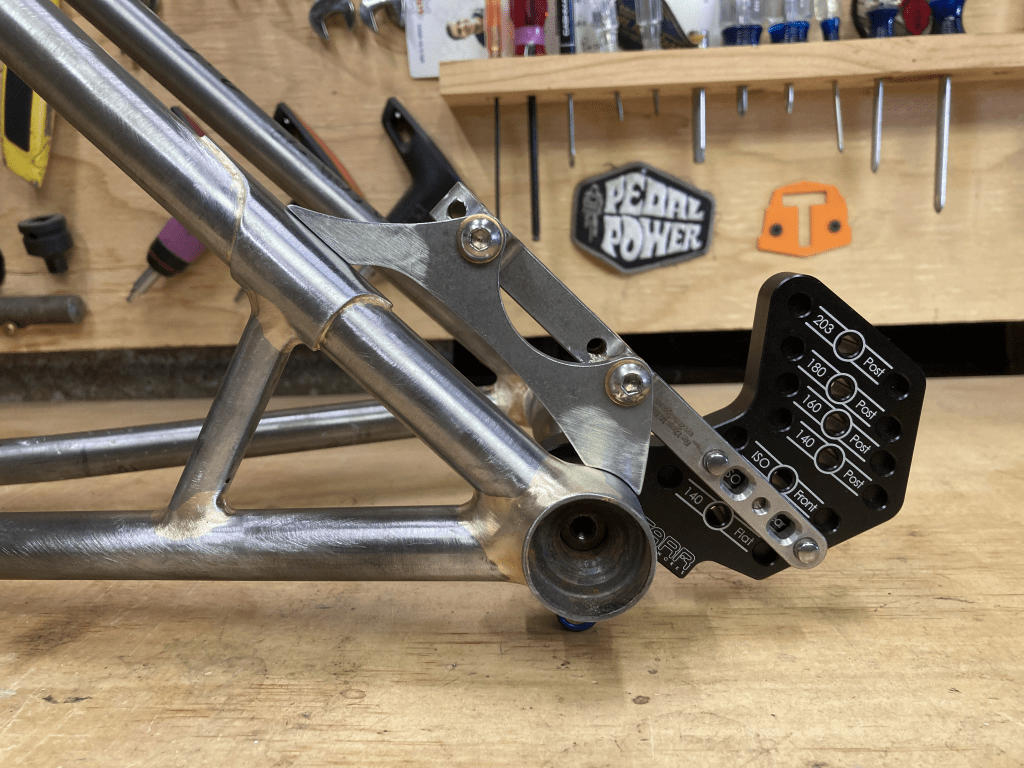
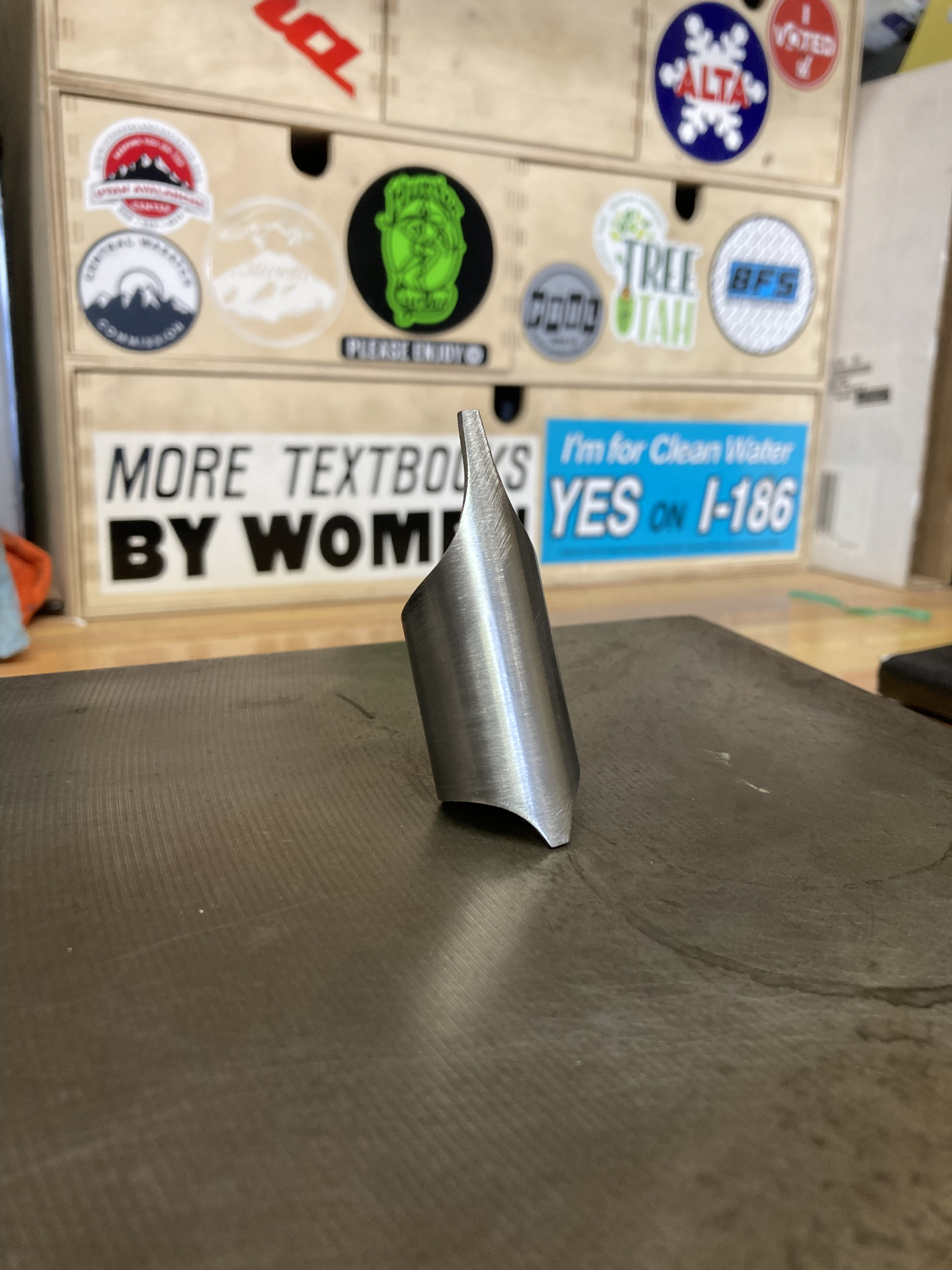
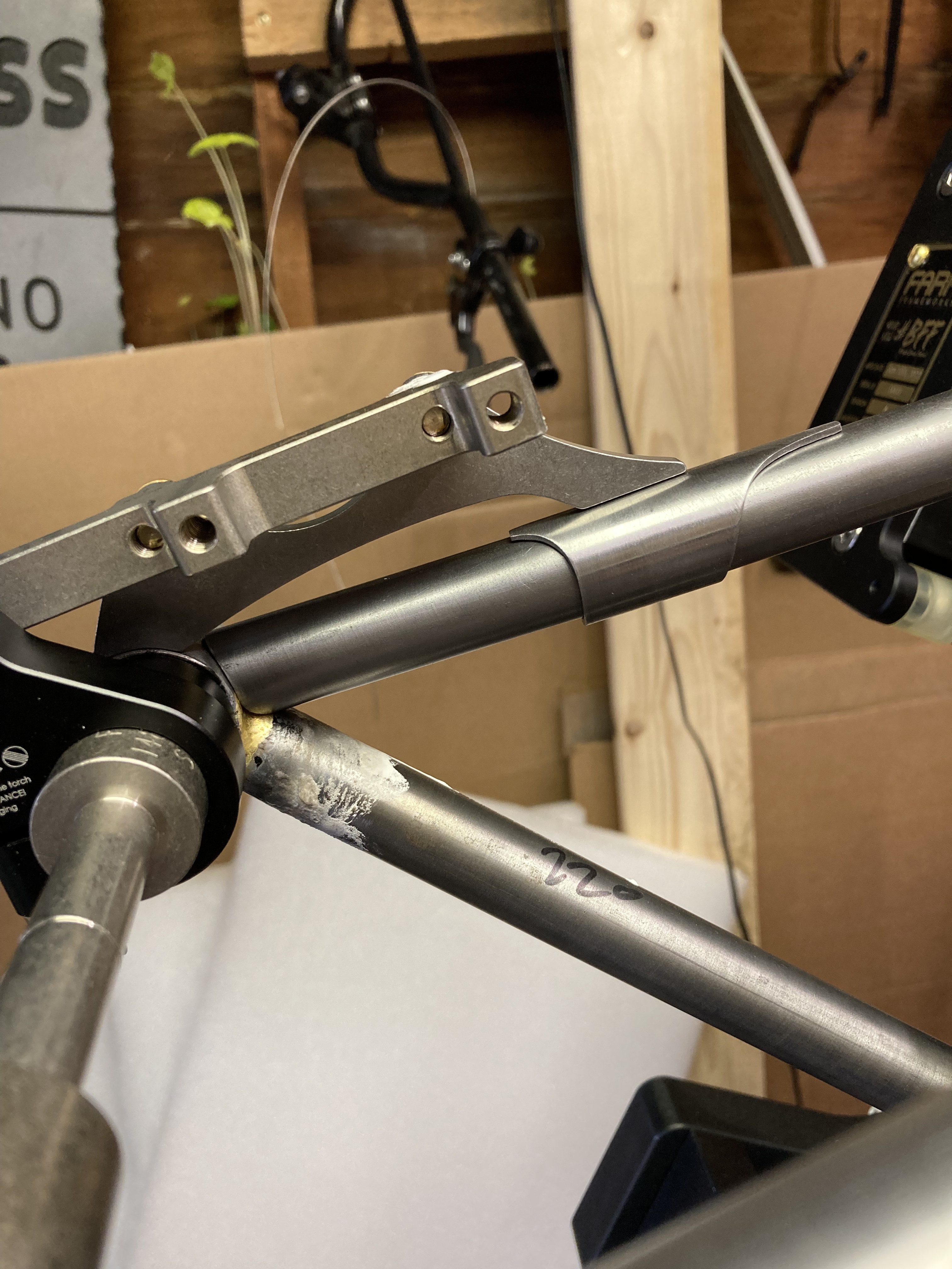
I used an SLM 3D printed 316L stainless chainstay yoke from Daniel Yang on this bike. This part is pretty cool. It solves a lot of problems around the bottom bracket in an elegant and light weight fashion. It is also the first metal 3D part I have held in my hand, despite my earlier work with CFD for 3D printed heat sinks. The fact that this part was stainless steel presented some new challenges. Unlike all of the other joints on this bike, I couldn’t use LFB filler rod and flux. Instead, I used Fillet Pro filler rod and Cycle Design Stainless Light flux. I can’t say I’m a convert, especially for the price of each, but I made it work. Fixturing this yoke in place also proved to be a challenge for my order of operations. I used the setup shown below to braze the chainstays to the yoke first, then I mitered the dropout ends, and finally I brazed the entire assembly together in the fixture.
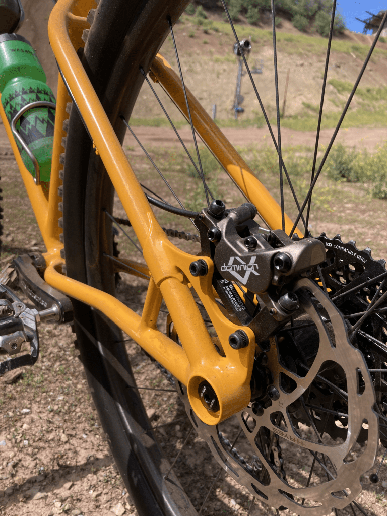
Next I mitered the seat stays. I had Pete Olivetti bend me these 3/4″ x 0.028″ stays on his Cobra bender, so I really couldn’t mess them up. Before attaching them to the frame, I brazed on a reinforcing lug for the disc brake tab. I will be using Hayes Dominion A4 brakes on this bike (which are enormous) so I want to take extra care to ensure that there is enough reinforcement to distribute the high stresses from braking.
Next I brazed the cable guides and stops on and did some last minute finishing. The final step before heading to the painter was to make the head badge and braze it on.
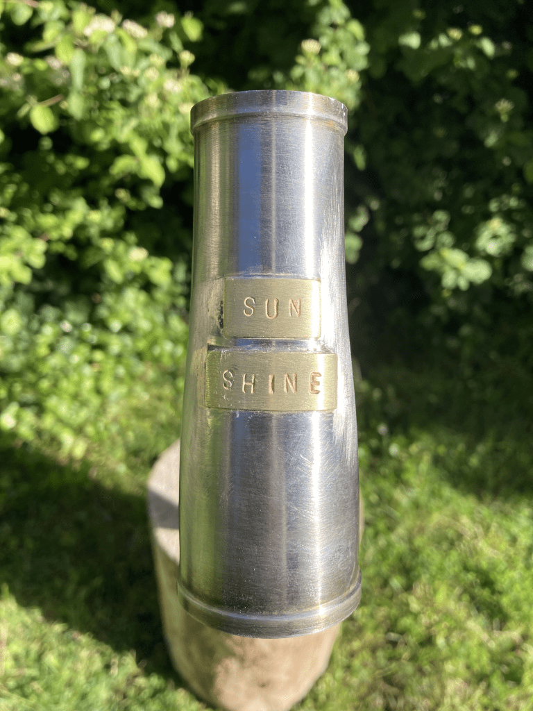
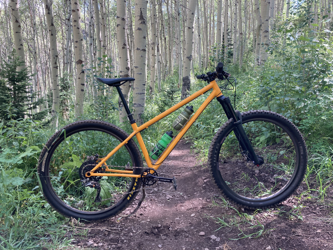
I had Ollie Cleveland at Dark Matter Finishing apply a coat of RAL1037 (Sun Yellow) to capture its summer spirit. Here’s the final product: