In my Junior year at the University of Utah, I took a mechatronics course. It consisted of two parts: a lab section and a semester-long group project. The lab section focused on designing, building, analyzing, and understanding general mechatronic systems. It covered sensors, actuators, and the use of computers for data capture and analysis. The semester-long group project was to build an autonomous robot that would navigate an obstacle course. Myself and 4 other students worked extremely hard on this project, and a breakdown of the course challenges and our design solutions for them is given below, in the order that the challenges appear in the obstacle course.
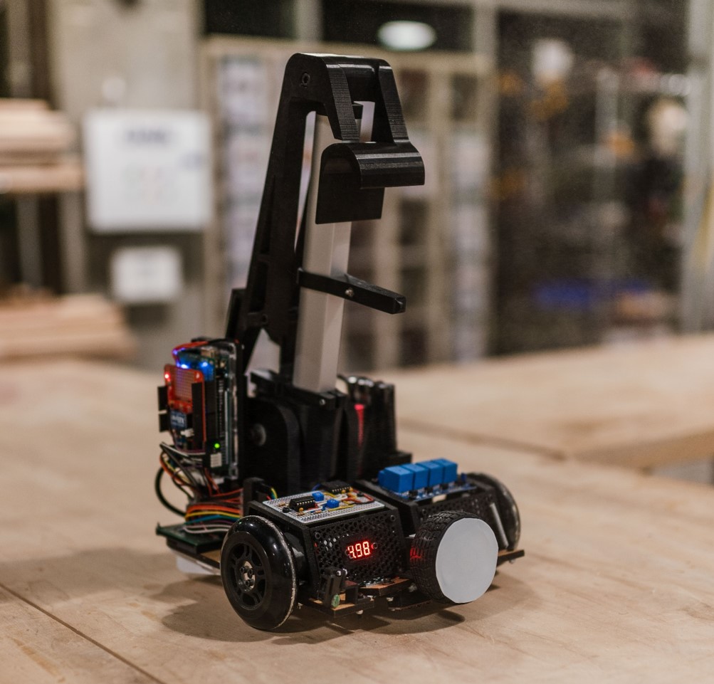
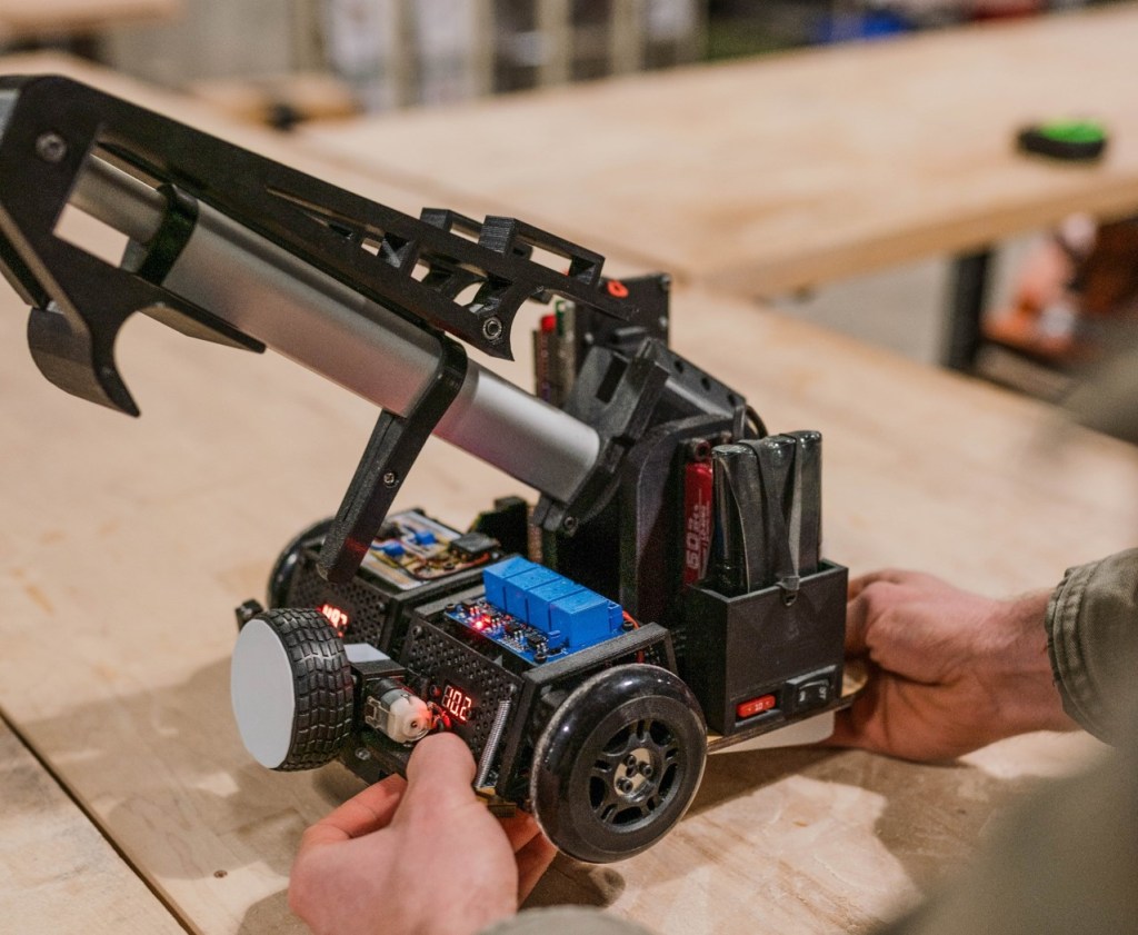
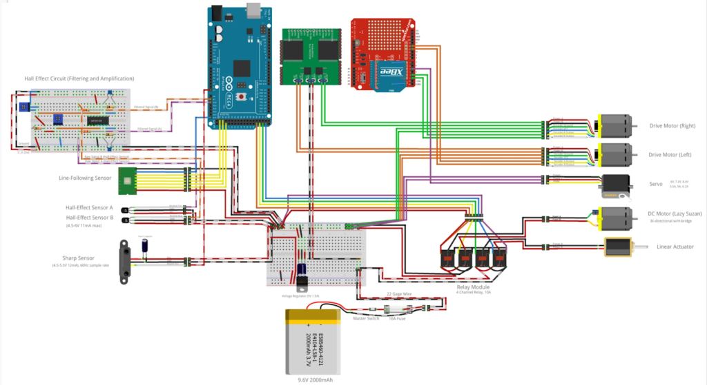
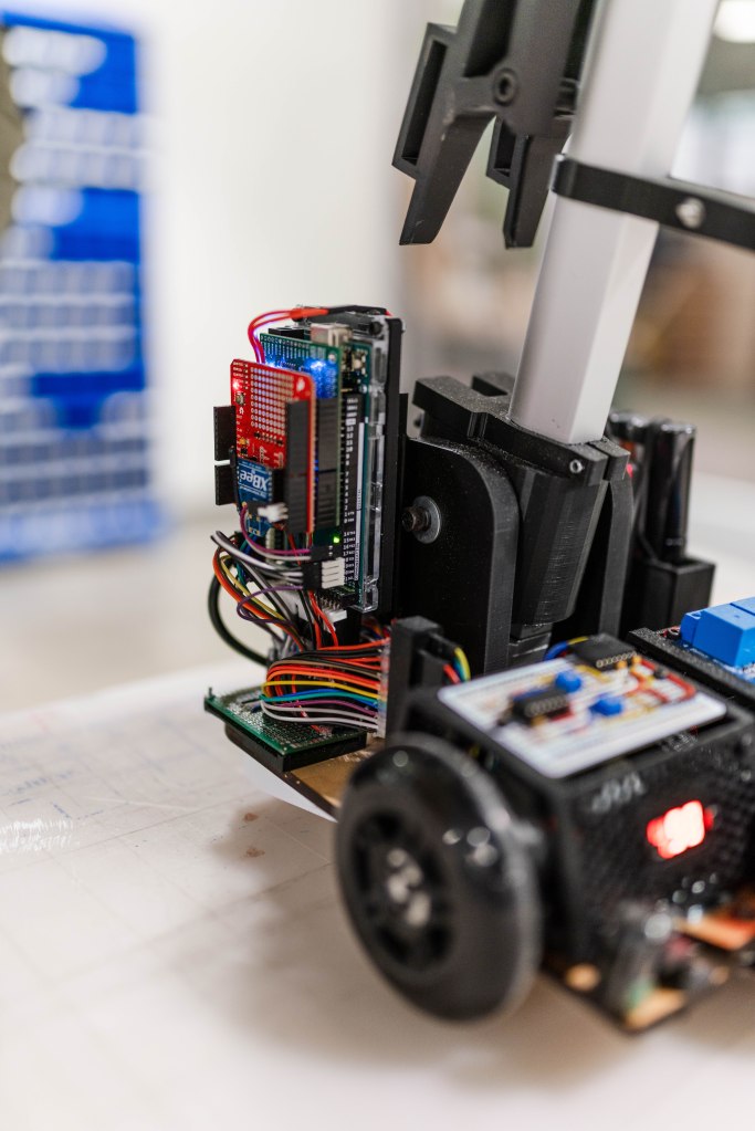
The robot is controlled by an Arduino Mega that we programmed. Commands are sent wirelessly from one of our computers to the XBee shield on the arduino. The commands tell the robot to start its routine depending on what obstacle it is placed on. Otherwise, the robot is completely autonomous.
A video of our competition runs can be found here, from 21:19 to 22:50. This run has some hiccups, but a video of the robot completing the first 3 obstacles in a row is at the bottom of this post.
Paddleboard:
The paddleboard is a flat surface with white walls on either side. It is able to rotate about the center so that if a robot is too close to one side of the paddleboard, the paddleboard will flip over and the robot will fall. A schematic is given below:
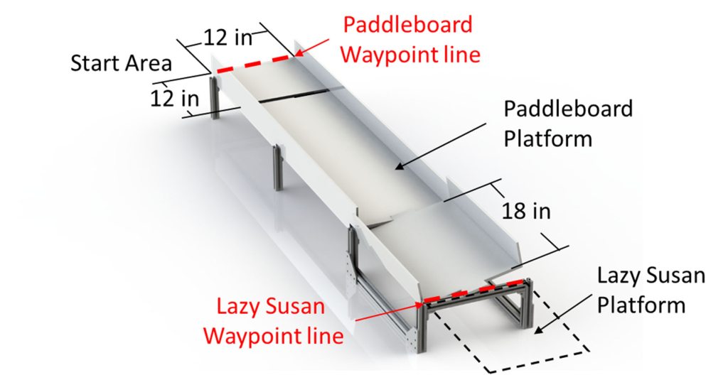
Our solution to navigate this obstacle and ensure we remained in the center of the board was to use an infrared rangefinder (Sharp GP2Y0A51SK0F) and PID control of our motors. The infrared rangefinder consists of an IR LED, and IR detector, and a signal processing circuit that converts the signal measured by the detector into an output voltage. This output voltage signal was digitally filtered with a finite impulse response moving average filter and then compared to a calibration curve from the manufacturer to give the distance of the sensor from the surface in front of it. The IR rangefinder we used has an effective range of 4-30cm, so we placed it on one side of our robot and measured the distance from the sensor to the edge of the obstacle course when the robot was centered on the course. With proper tuning of our PID controller we were able to successfully keep the robot on the center of the paddleboard and ensure that it drove across safely.
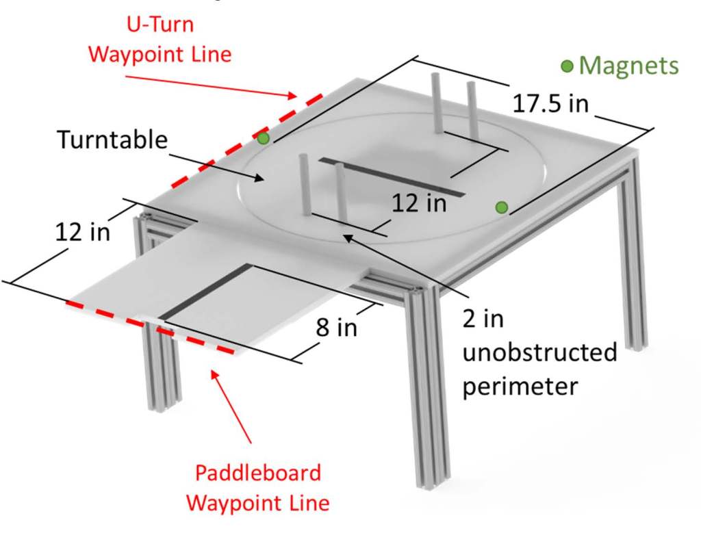
Lazy Susan:
The Lazy Susan is similar to the home object of the same name. It is a freely rotating platform onto which the robot must drive. The Lazy Susan is oriented such that when the robot approaches it, there are two aluminum posts blocking the robot from driving onto it. Therefore, the robot must rotate the Lazy Susan 90 degrees before being able to drive on. The robot must then rotate itself and the Lazy Susan another 90 degrees so that it can drive off of the Lazy Susan and onto the next obstacle.
There is a magnet underneath the turntable portion of the Lazy Susan that is aligned so that the robot may identify when it is able to drive onto the turntable. There is another magnet under the exit of the obstacle so that the robot may identify where to leave the turntable.
This one was hard. Our solution began by following the black line on the center of the course until it ended. Then, we used quadrature encoding and PID control on each of the drive motors to propel the robot forward in a straight line so that it was positioned over the rim of the turntable. Next, we used a servo to move a lever down onto a hinged front bumper. The hinged front bumper had a rubber wheel mounted to a motor that would then rotate, spinning the turntable.
While the motor was spinning the turntable, two Hall-effect sensors mounted equidistant but in opposite directions of the center of the robot were comparing their signals to determine the proximity of the magnet under the turntable. When the signals were approximately the same, the front motor stopped immediately and the robot drove onto the turntable. While driving, the robot used the same quadrature encoding PID to drive until the black line on the center of the turntable was detected. The robot then used a QTR-8RC IR Reflectance Sensor Array with PID control to keep the robot centered over the line. When the robot got to the other side of the turntable, the same hinged front bumper was pressed again so that the front wheel was in contact with the ground, and the motor was turned on and turntable began to spin with the robot on it. The same process as before with the hall effect sensors was used to stop the turntable so that the robot could drive onto the next obstacle.
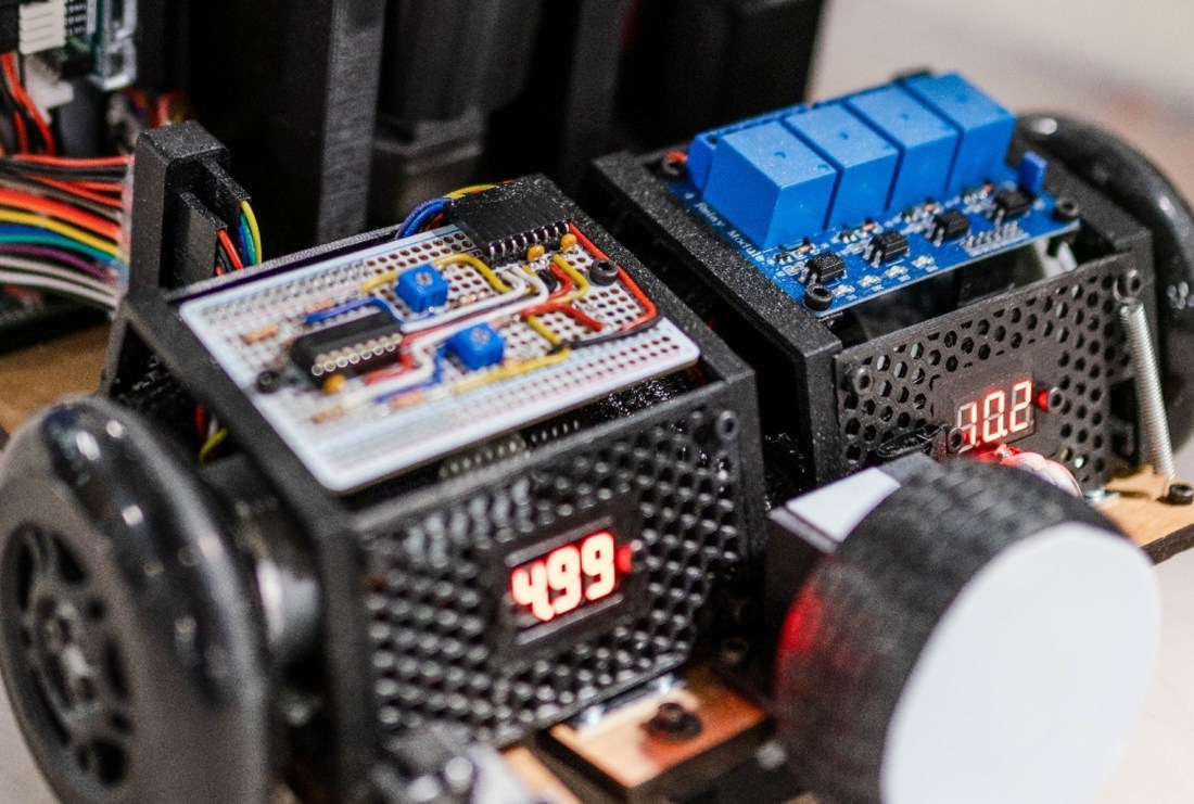
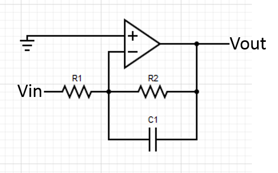
Hall effect sensors are, in general, noisy devices. To fix this, we placed an active low-pass filter (shown below) directly after the sensor so that the information coming from it could be interpreted with more precision.
U-Turn:
The U-turn is a U-shaped curve in the course. The robot must drive around the curve without falling off on either side. There is a black line in the center of the course.

The same QTR-8RC IR Reflectance Sensor Array described above was used to measure the position of the robot over the black line in the center of the course. This position information was used with PID control to drive the motors such that the robot was always adjusting so that it was centered on the course. This allowed it to make the necessary turns to complete the obstacle.
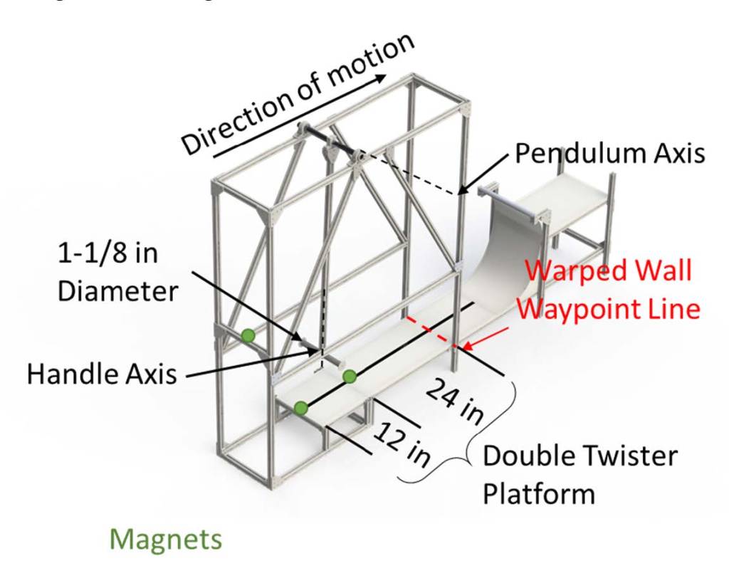
Double Twister:
The double twister is a pendulum with two degrees of freedom. The first is the axis that the pendulum swings about. The second is the axis the handle spins around. The two axes are perpendicular to one another. The robot must attach itself to the arm of the swing and descend to the lower portion of the course. The robot must then remove itself from the arm of the swing and continue on the course.
The robot was driven forward by the same method used on the U-Turn and was stopped by this method when the QTR sensor was driven over the edge of the course. All of the signals went to zero so this condition was easy to identify. The robot then extended a linear actuator with a hook attached to it, raised the servo that the linear actuator was attached to, and retracted the linear actuator. This pulled the robot up to the handle, which allowed the robot to swing down to the platform below. The hook was shaped so that it simultaneously grabbed onto the round handle and the square extrusion of the pendulum. This locked out the rotation of the handle, turning the double twister into an ordinary pendulum. Almost immediately after beginning the swing to the lower portion of the course, the linear actuator was extended, while the robot was still in the air, so that when the robot reached the lower platform it was almost free of the swinging arm. The robot then continued to extend the hook until it could drive forward and free itself of the hook. Figuring out the timing of this maneuver took quite a bit of trial and error, but in the end, we were able to complete the obstacle every time we tried.
Warped Wall:
The warped wall is a curved wall that is 19” high. The robot must raise itself entirely 6” above the platform and remain there by grabbing onto the top of the wall.
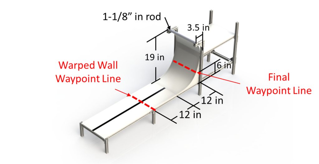
The robot continued to drive away from the landing area of the double twister while simultaneously raising its linear actuator. When the robot reached the end of the black line at the center of the course below the warped wall, the actuator was fully extended. The servo was then actuated so that the arm swung back towards the front of the robot, catching the hook onto the warped wall. The actuator was then retracted so that the robot was lifted above the 6” clearance mark, completing the course.
Ultimately, we came 2nd out of 10 teams in the class-wide competition. Our robot won the “cleanest wiring” award. It’s not hard to see why.