Spark plasma sintering (SPS) is a materials synthesis technique that allows for sintering at high temperatures and pressures. Through joule heating and above-atmospheric pressures, the time that it takes to sinter a material is reduced considerably with an SPS process. Additionally, since sintering times are drastically reduced, grain and particle size can be kept as small as they were prior to sintering, whereas standard sintering routes often include annealing and Ostwald ripening. These phenomena are not desirable for many novel materials where controlling particle size and grain size are of interest, such as in the field of thermoelectrics.

Spark plasma sintering is useful because it allows materials to achieve near their theoretical density. This is particularly important for making precise thermal and electrical measurements, such as those required to describe a thermoelectric’s figure of merit.
When I joined the Sparks Research Group at the University of Utah, the group had no such machine. What it did have was the design and some materials from a previously graduated senior in the MSE department for a spark plasma sintering machine which had never been completed. All that was present was a 1989 Instron 4206, some Matsusada DC power supplies, and a Kurt J. Lesker water-cooled vacuum chamber sans-vacuum pump and sans-water-cooling. And it had Jake. Jake works harder than you or I or anyone we know does.
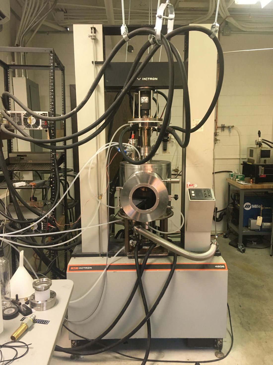
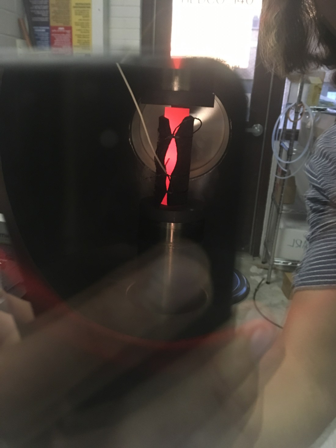
The premise of the machine is to apply pressure to two graphite punches in a graphite die while running a large DC current through the die to joule-heat the material inside of the die. All of this occurs in argon or under vacuum. While this sounds relatively straight forward, I can assure you that it is not. This machine consists of three separate water systems, two gas systems, two electrical systems, and one mechanical system. The machine occupies nearly an entire room. The machine is able to pass 2400A through its pistons under a vacuum on the order of a few millitorr. This is a complicated machine.
The machine was disassembled when I arrived in the winter of 2018. It had been previously assembled by Jake and he had successfully used the machine to SPS a copper pellet from copper powder. However, the water-cooled pistons on the machine which deliver the force to the graphite die punches were not lined with anything, and given the extreme environment and the ordinary water running through them, they corroded irreparably and ruined the water system and the pistons themselves, which is why the machine was in its disassembled state when I initially encountered it.
The first thing we tackled was the creation of new pistons. We had these custom made for our specific machine by Kurt J. Lesker and then had them lined with a fluoropolymer to discourage corrosion in the extreme environment. They are then coated in what is essentially 3” diameter polyolefin heat-shrink tubing to ensure that they do not make contact with the vacuum chamber during loading and short the power circuit.

Next, we started on the vacuum system. We assembled the chamber, an 18” diameter, 18” tall stainless-steel cylinder with two quartz viewing portals, two entry-points for opposing pistons from the Instron, and two ports for gas lines and pressure gauges. The chamber had 6 copper o-rings and four rubber o-rings to ensure that a high vacuum was maintained during its operation. Each o-ring is accessible by removing 12 316 stainless-steel screws, nearly all of which are positioned such that it is nearly impossible to get a hand on them, let alone a tool. Not to mention the chamber weighs close to 150lbs.
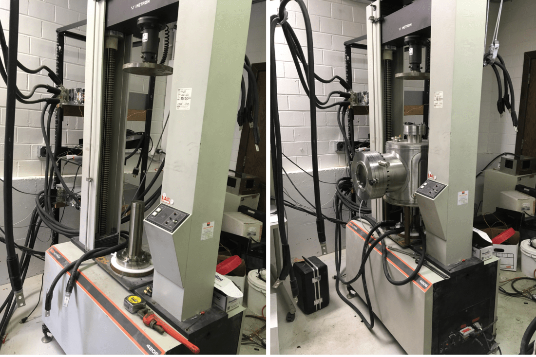
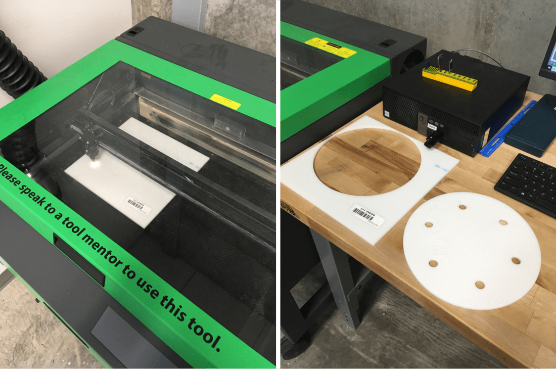
The vacuum system was initially assembled on the ground but ultimately had to be transferred into the loadframe of the Instron. However, the pistons are also made from 316 stainless-steel, so in order to ensure that the large current for sintering did not pass through the load frame, some insulation between the pistons and the load frame was necessary. To do this, I laser cut some ¼” thick Delrin discs to match the bolt pattern of the piston and load frame and sandwiched them in between the two. The screws that hold the bottom piston securely in place are made from nylon to ensure that they also are not conductive. Nylon would not be a suitable material for the screws holding the top piston to the crosshead of the Instron because the piston, the water inside of the pistons, and the 6 350MCM cables attached to the piston are near 70 lbs. As a result of this, we had to use fiberglass threaded rods to attach the piston to the crosshead and ensure that it is properly insulated from the Instron.
Once assembled and in place, sealing the gas system and preventing it from leaking was relatively quick work with a helium source and a helium wand for leak detection. The system is now able to hold a vacuum of a few millitorr for a few days.
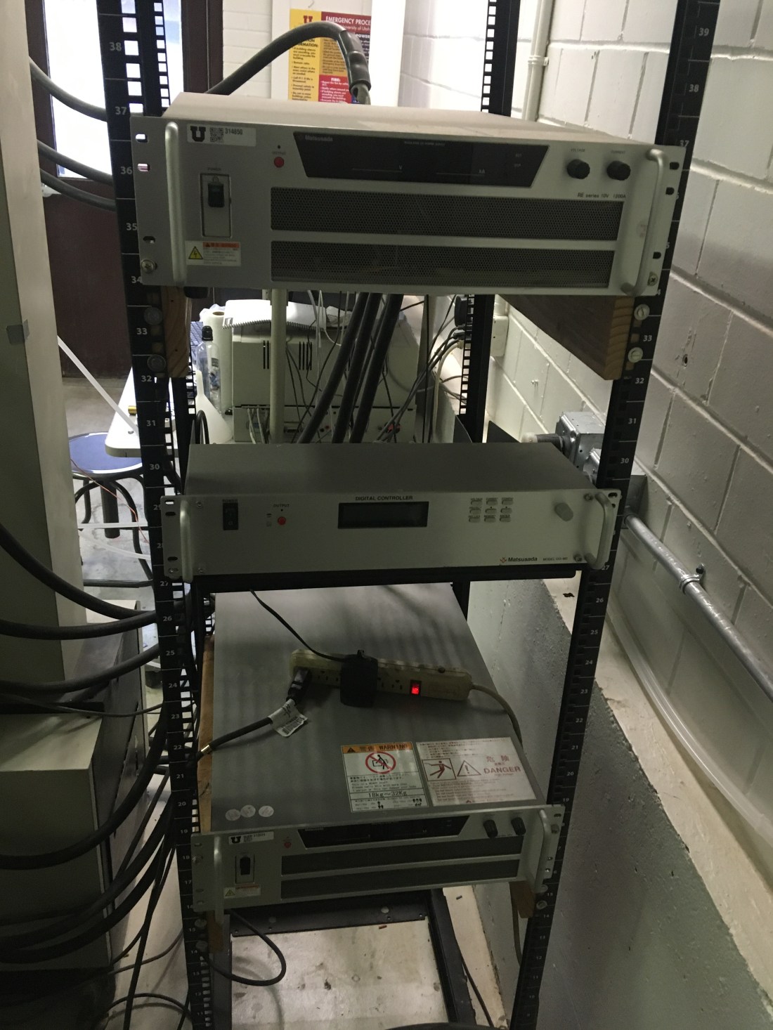
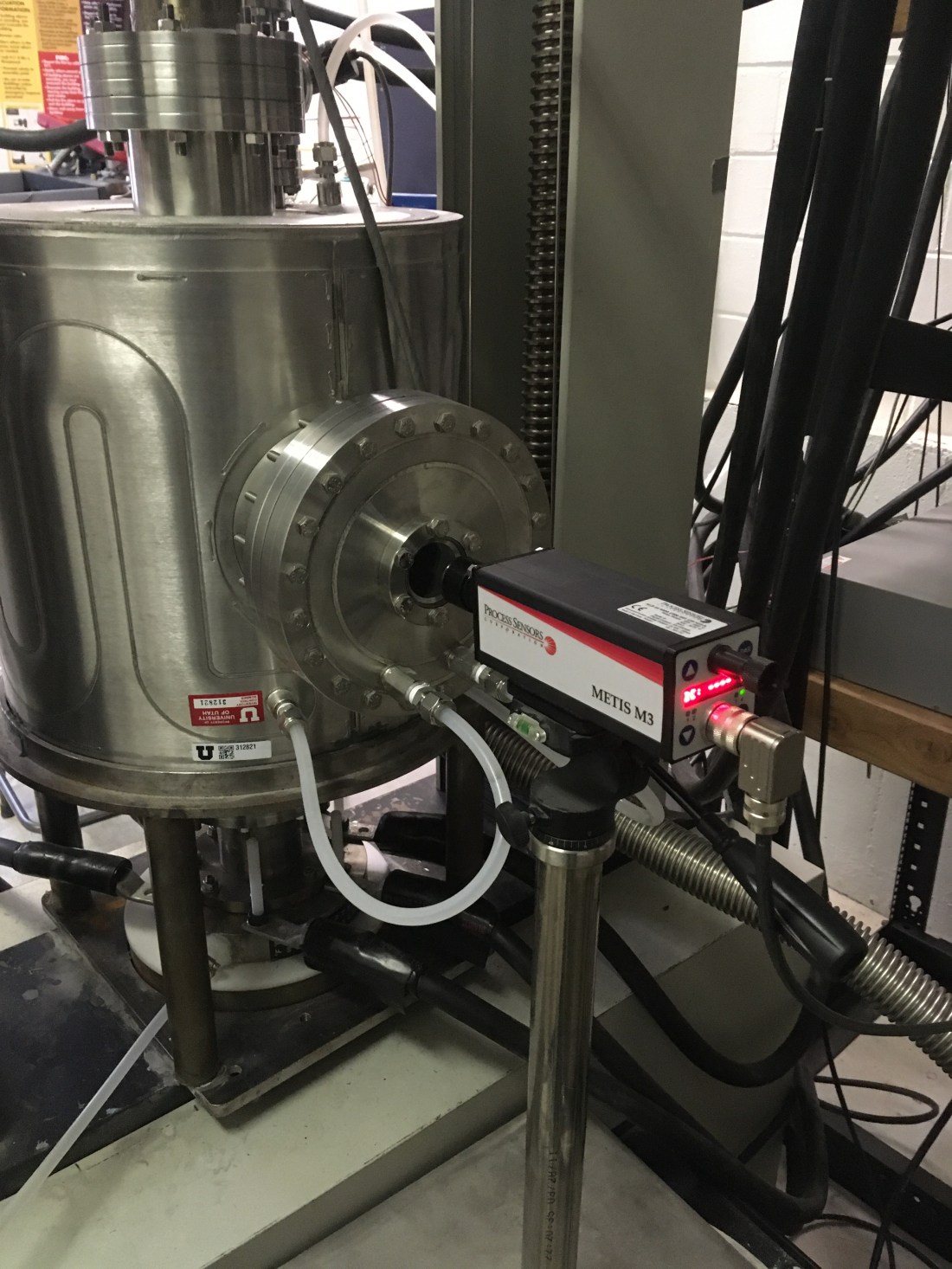
Next, we assembled the power electrical system. This was scary. Our power system consists of 2 Matsusada 1200A 10V DC current sources, a digital controller, and 12 350MCM cables. This thing can turn a lot of power into a lot of heat really quickly. There are 6 350MCM’s leading to each piston and they are attached by the same screws that hold the pistons to the Instron. This system is PID controlled by an in situ thermocouple and an ex situ pyrometer that measure the temperature of the die in the press. They feed the controller temperature inputs and the controller dictates the current required to achieve the desired temperature.
The system that was by far the most problematic and time consuming on this machine was the water system. Because of this machine I have disassembled and reassembled a Thermofisher Scientific Isotemp water chiller more times than I can count and certainly more times than I would like. Due to the corrosion incident the machine had prior to my intervention, the chillers had taken a fair amount of abuse in the form of corrosion products floating in the process water by the time we ran them again, so they were unhappy to be put to use again. One chiller refused to operate entirely, even after several replacements of several components, and we ultimately decided to forgo the use of a chiller and just use house water instead.
The house water cools the vacuum chamber because it theoretically will never get too remarkably hot at any one point. Since the chamber is evacuated, the only heat transfer it experiences is radiative heat transfer, which attenuates according to an inverse square relationship. This is to say that the chamber should ideally never reach a temperature over approximately 60C when cooled. The pistons however are in direct contact with the graphite die which in some cases is at a temperature of 1000C. Because of this, they need to have a higher cooling rate and the process water cannot have ions which could promote corrosion. As such, the chilling water for the pistons is deionized and sent through a closed loop Thermofisher Scientific Isotemp water chiller which itself is cooled by house water. Through iterations we were finally able to achieve an efficient and dependable cooling system for the machine that made it safe to operate at temperatures in excess of 1000C and currents in excess of 2000A.