
I wanted a drill press, and I wanted one where there weren’t any corners cut in its making. As far as machine tools go, this is synonymous with “old” and “made in America.” I lurked around on Craigslist for a month or so until I found a good deal. I contacted the owner and the very same day I was in my truck headed up to Ogden. From what I could pick up, the owner was a man in his late 70’s who was moving and getting rid of his woodworking equipment that he’d had for the last 30-60 years. For $100 I bought his workbench, radial arm saw, Westinghouse bench grinder, two vises, and his Rockwell Delta Homecraft drill press. His shop was in a basement and all of the tools were bolted to the work bench. I had no use for the work bench so I demolished it in the basement and loaded it into my truck in pieces, along with the rest of the tools.
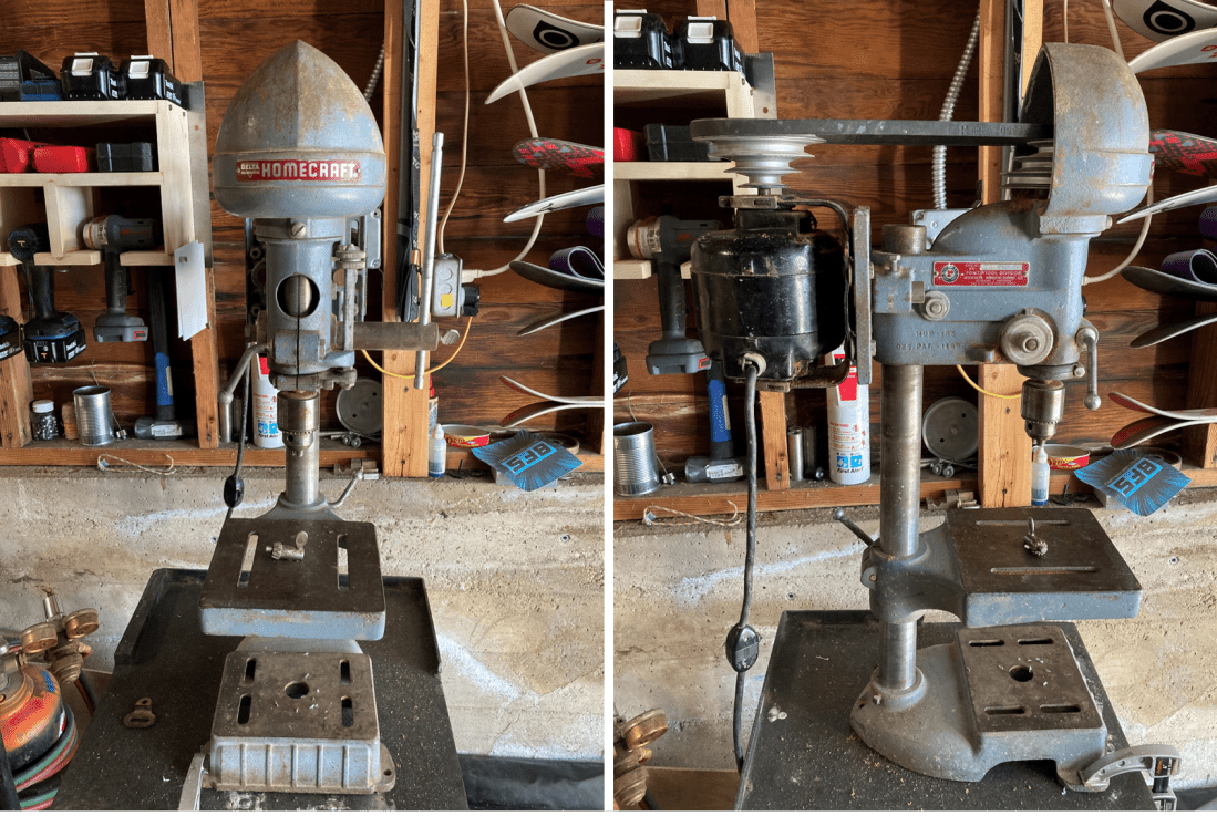
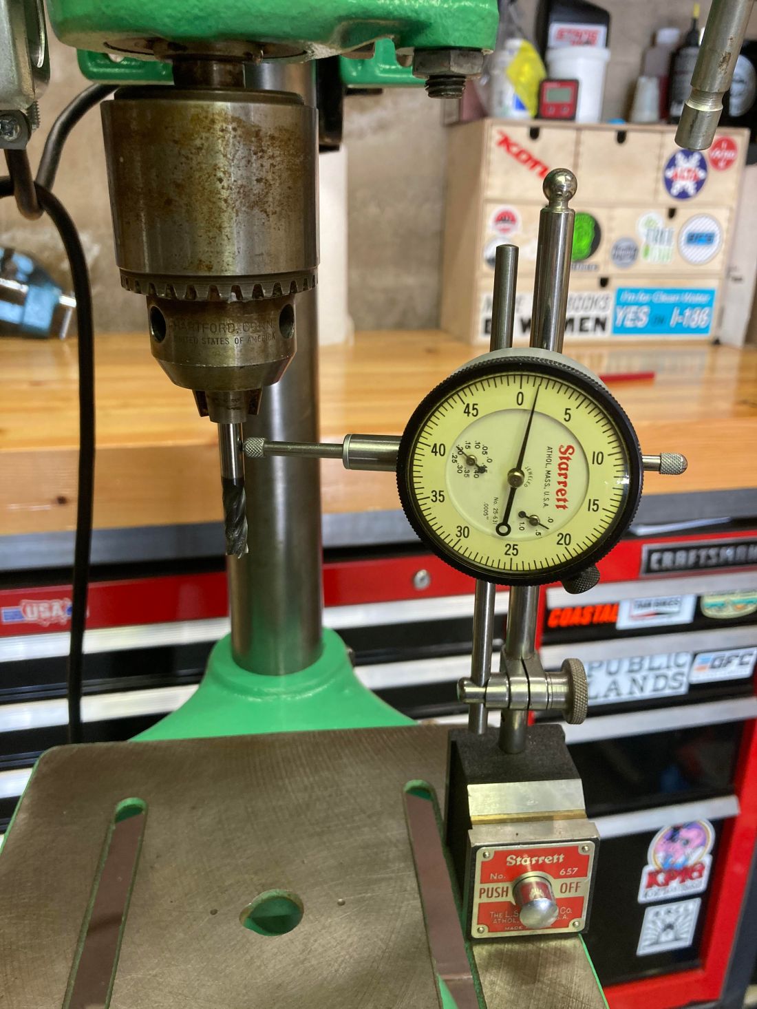
Once I had the drill press back in my shop, I did some inspection to see just what I had bought. Based on some internet research, the machine is a Delta Homecraft 11-120 11” Drill Press that was manufactured in Milwaukee, Wisconsin in 1953. It even came standard with a Jacobs chuck. Old Wisconsin steel with a chuck from Connecticut is exactly what I wanted. I checked the runout on the spindle and chuck by chucking a 1/4” endmill and setting a dial indicator perpendicular to the rotational axis of the spindle. 0.0055” of runout. Not perfect, but good enough for a drill press with a three-jaw chuck.

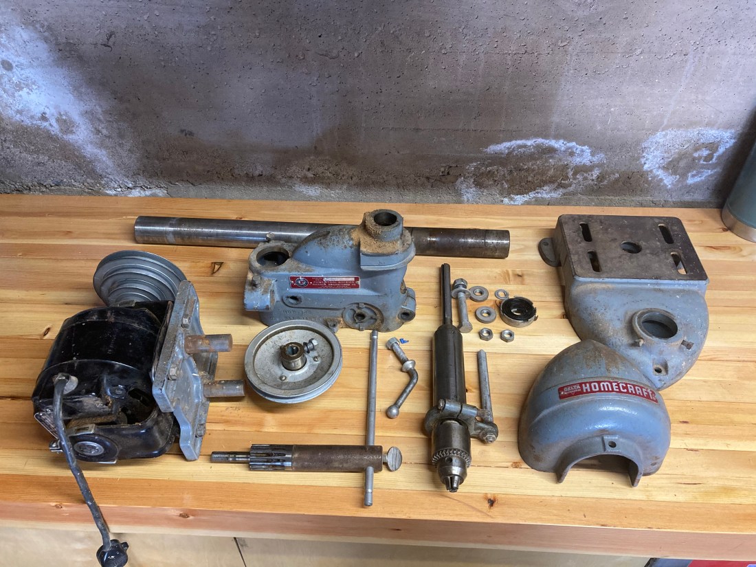
Knowing that it was at least in good working order, I decided to give it a bit of a restoration. I took the entire machine apart and vigorously cleaned every surface with acetone and a wire brush.
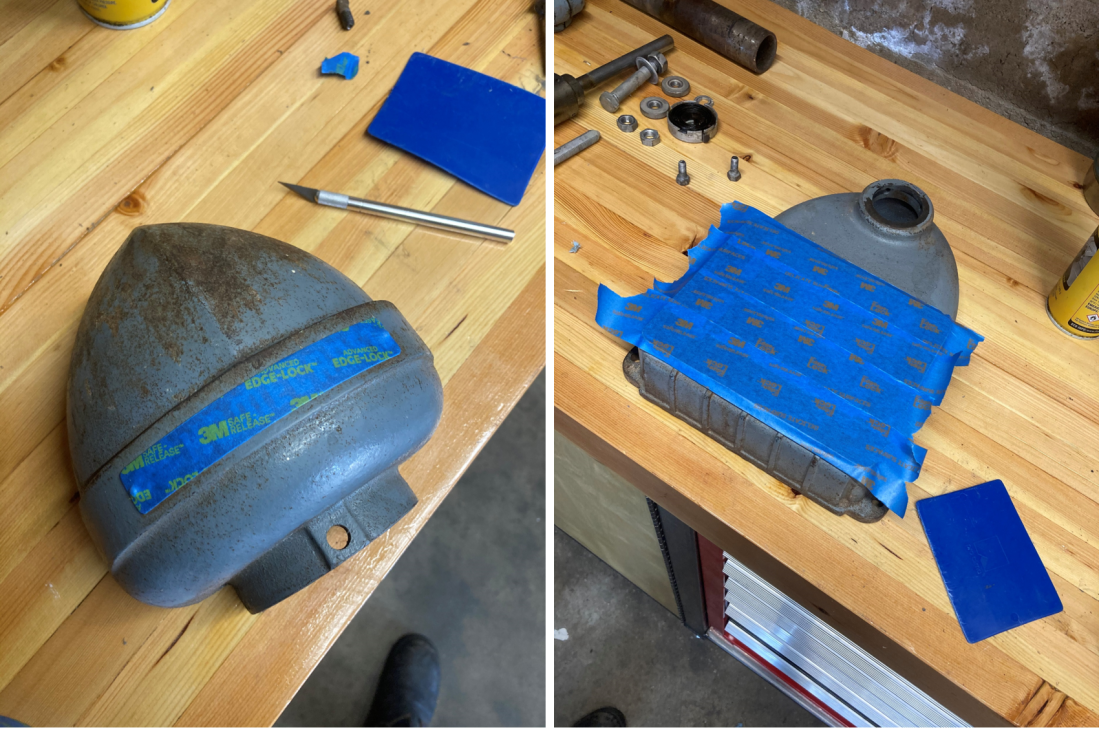
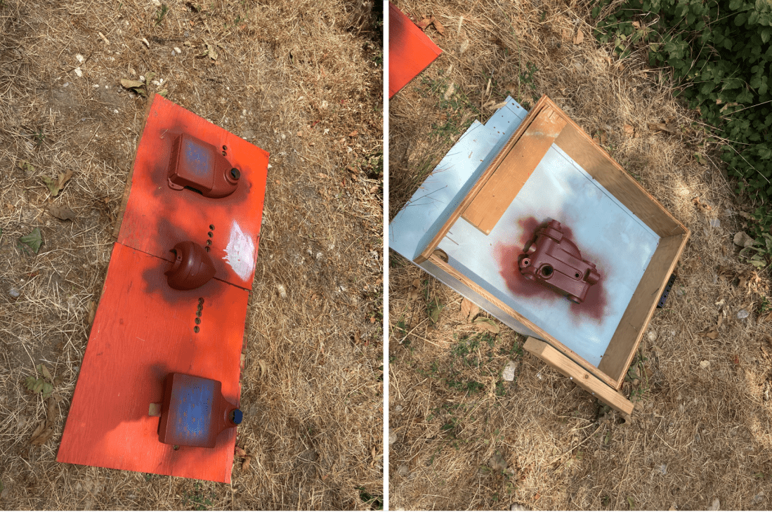
I masked over the important surfaces and primed and painted all of the castings. While doing my internet research I came across a forum post that said “All drill presses should be gear grey or gloss black, period.” I disagree. The original machine was gear grey but I don’t like that color. Instead, I painted it a similar color to a Nardini lathe that Paragon Machine Works had when I worked there. I’ve come to call it “machine green.”
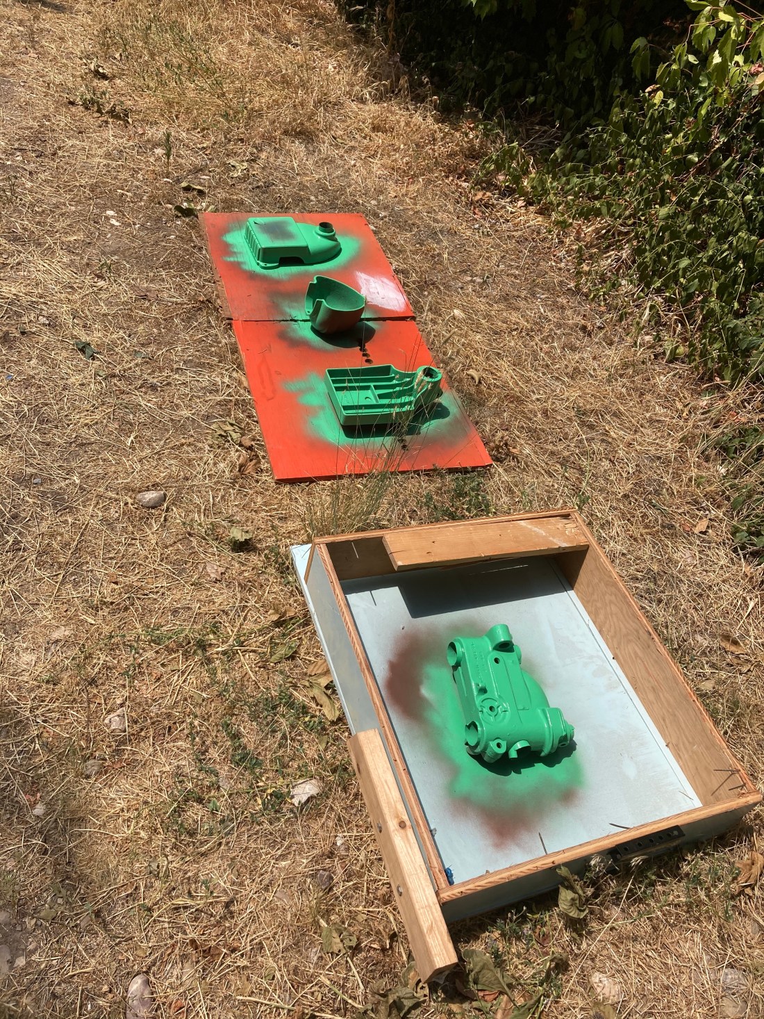
While I was waiting for the paint to dry, I took a wire wheel on an angle grinder to the more rusted out pieces of the machine. I then coated them in Fluid Film, which is the superior surface corrosion inhibitor. Don’t bother with anything else, it’s not worth your time or money.
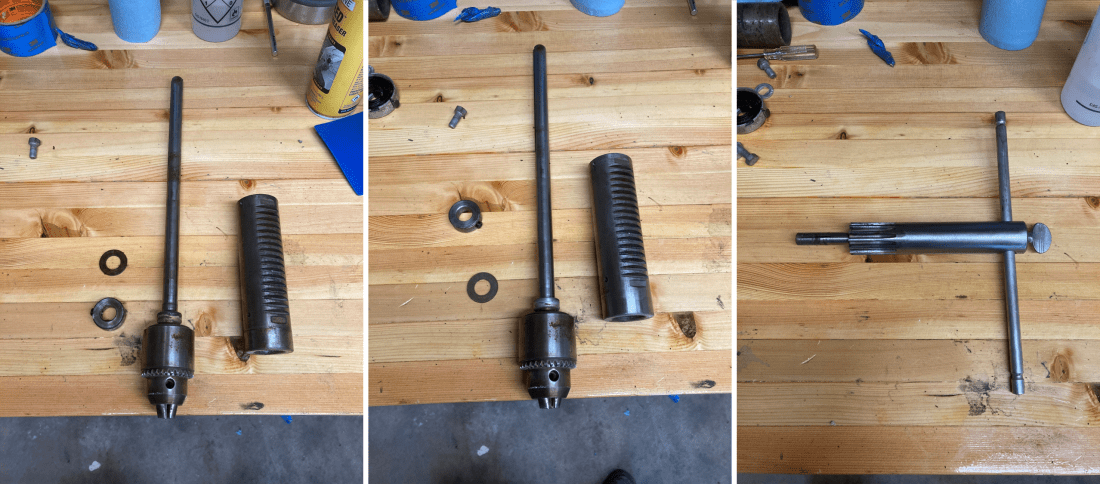
I disassembled the spindle and quill and cleaned them both thoroughly. Grease is a mixture of oil and wax, and when those two separate after many years the result is ugly and sticky. The bearing that the spindle pulley rides on was full of this junk, so I cleaned all the waxy residue out with acetone and a pick and checked all of the surfaces for wear and damage. Luckily there was none.
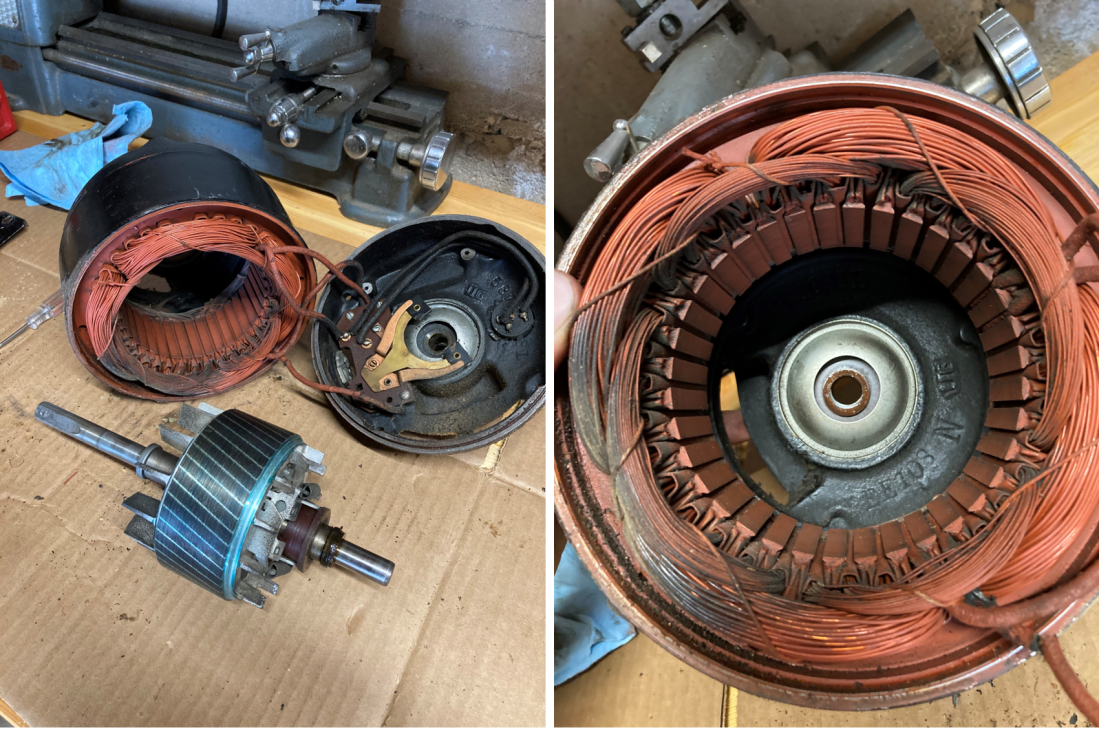
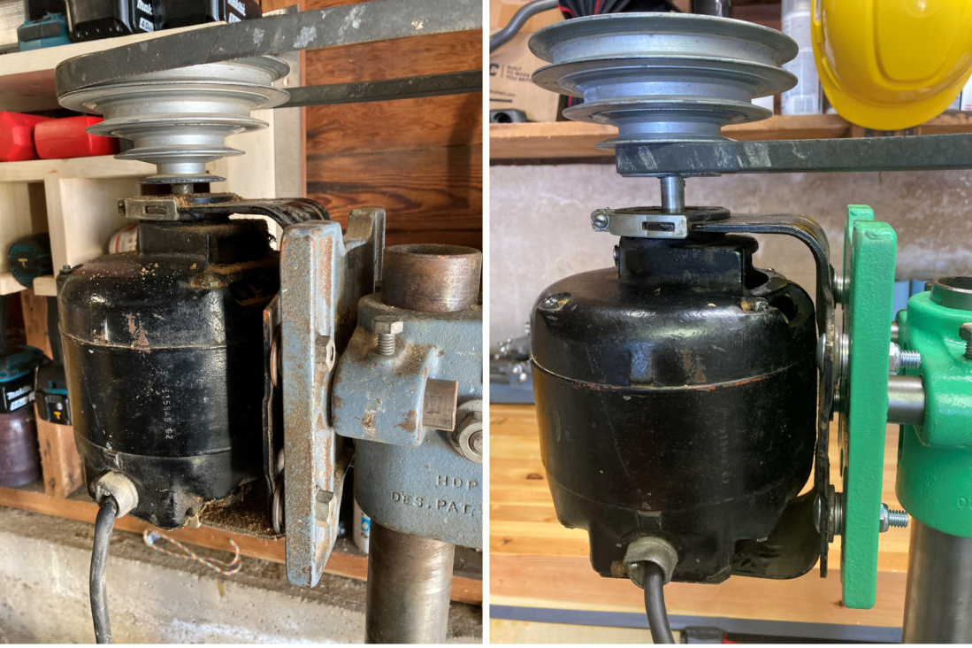
The motor is a General Electric 1/6 HP 3A 115VAC motor made in the USA. I took it apart to see what kind of wear there was and what I could replace to make it last longer. There really wasn’t much wrong with it other than some decaying insulation on one wire.
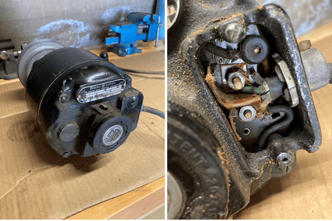
This motor is a repulsion-start induction motor, which I think is pretty cool. Generally, an AC motor requires more than one power phase to start. This is why its extremely common to see start capacitors on newer AC motors. The discharge of the capacitor on starting creates another phase that allows the motor to start. However, this motor does not have a start capacitor. Instead, it uses brushes to bring itself up to speed, and then a centrifugal switch engages and shorts the brush circuit, directing power to the main armature. A brilliant and elegant solution that will last nearly forever, since the brushes are only in contact with the commutator for fractions of a second on startup.
Once I cleaned it out and reassembled the motor, it was good to last another half of a decade. That said, it’s less powerful than I’d like for it to be, so I may swap it with a Century 1/3 HP motor I have lying around. Time will tell.
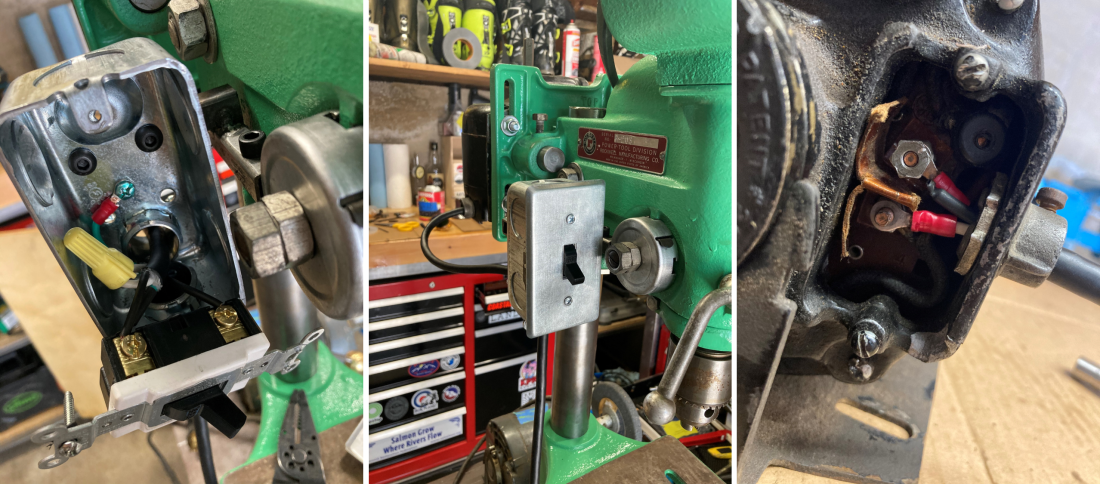
Not only did I not like the original on/off switch, it was extremely unsafe. In the event of an accident, it should be easy to find and actuate the power switch. The original switch was both hard to find and difficult to use.
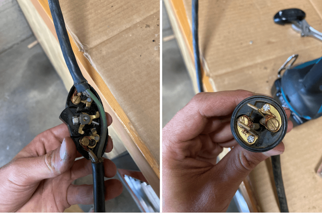
To fix this, I wired in a new switch. The original motor/machine was not grounded, which I did not really like. After consulting an electrician friend, I added a grounding wire to the machine when I added the switch, as well as a new power cable. I put ring terminals on the motor connections because I was bothered by the half-assed job done by the original owner. The result is a much safer and a much easier to use machine than the one I bought.
With the paint dry it was time to reassemble. I packed every moving part with Phil Wood Waterproof Grease and put the whole thing back together. Not too complicated.
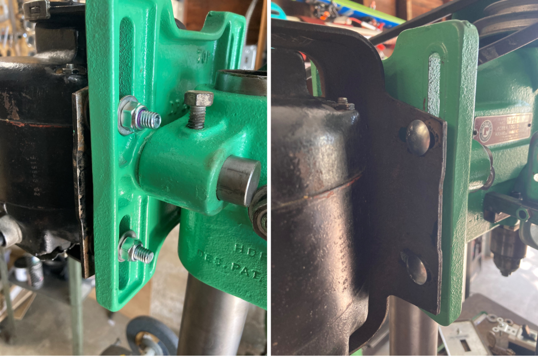
I replaced the motor mounts with new zinc plated carriage bolts and nylok nuts. Do it once, do it right.
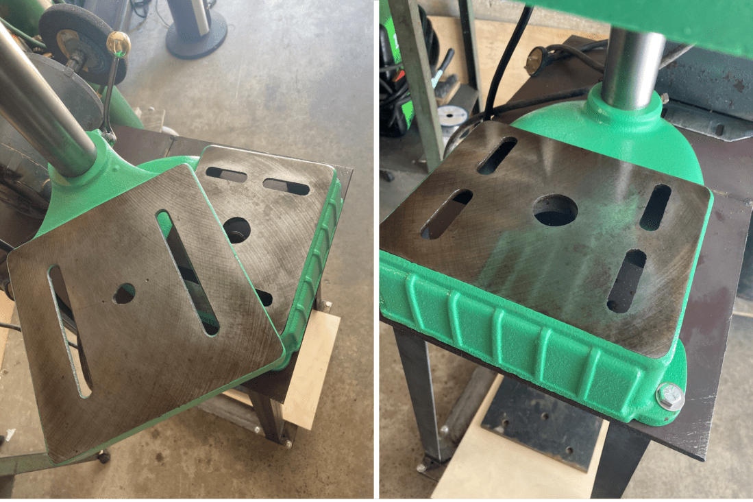
I stoned the base and the table to knock off the high spots and remove some of the rust. Always worth it, if not just for the looks.
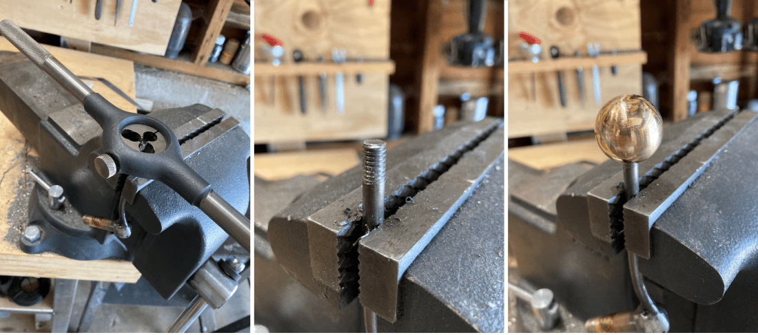
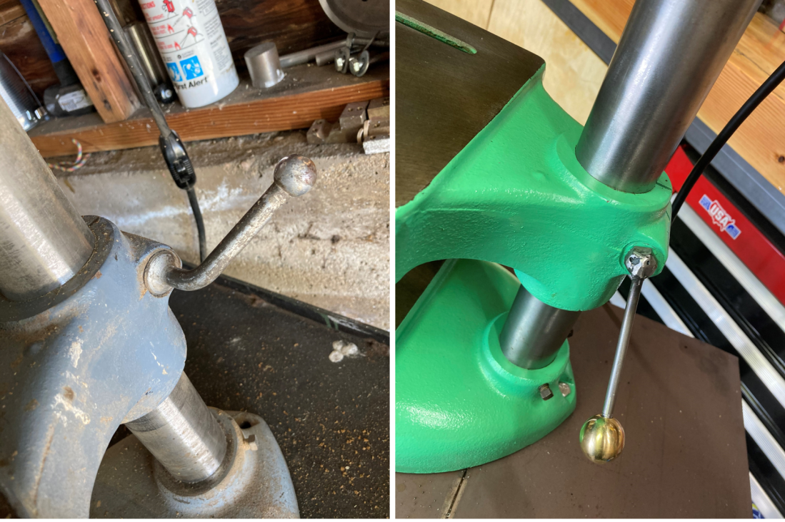
I didn’t like the table adjustment screw so I welded some 1/4″ round bar onto a hex head screw, cut some threads into the end, and attached a brass ball knob from McMaster Carr.
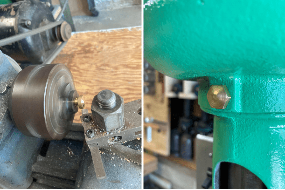
As a finishing touch I turned down a hex head brass screw on my hobby lathe to make it look nice.
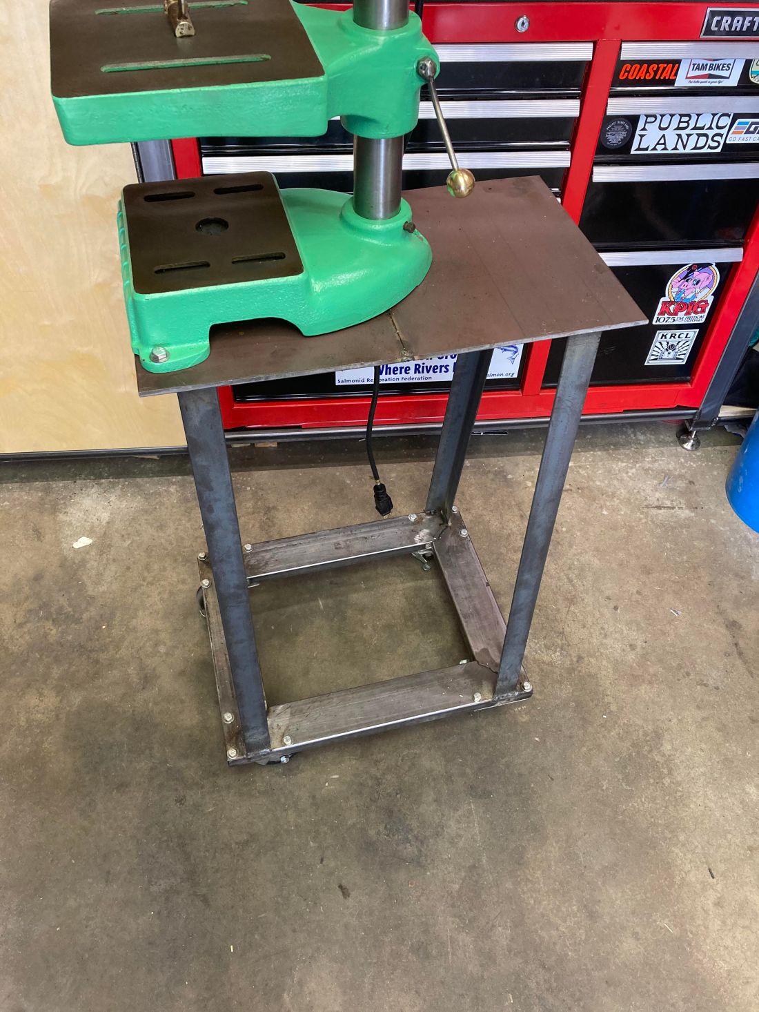
Now that I had the machine ready to go, I needed a place to put it in my crowded shop. The bench that the original owner had it on had nice casters, so I kept those and welded a table to sit on top of them.

This way it is on wheels and can be moved out of the way if need be. My metal supplier had a sale on ¼” plates so I got some and welded them together to make the top surface. Welding the ¼” plate tested the very upper limits of my 110V FCAW machine and I learned a lot about how to control the heat and minimize warping. All in all, the table came out level, plumb, and true. It seems like very welding challenge I’ve encountered can be solved with a cleverly devised tacking sequence. Someday I may make a cabinet to go under the drill press, but for now I will leave it empty. To match all of the other tables in my shop, I left the legs bare.
Finally, some before and after shots of the machine. I’m pleased with the result.
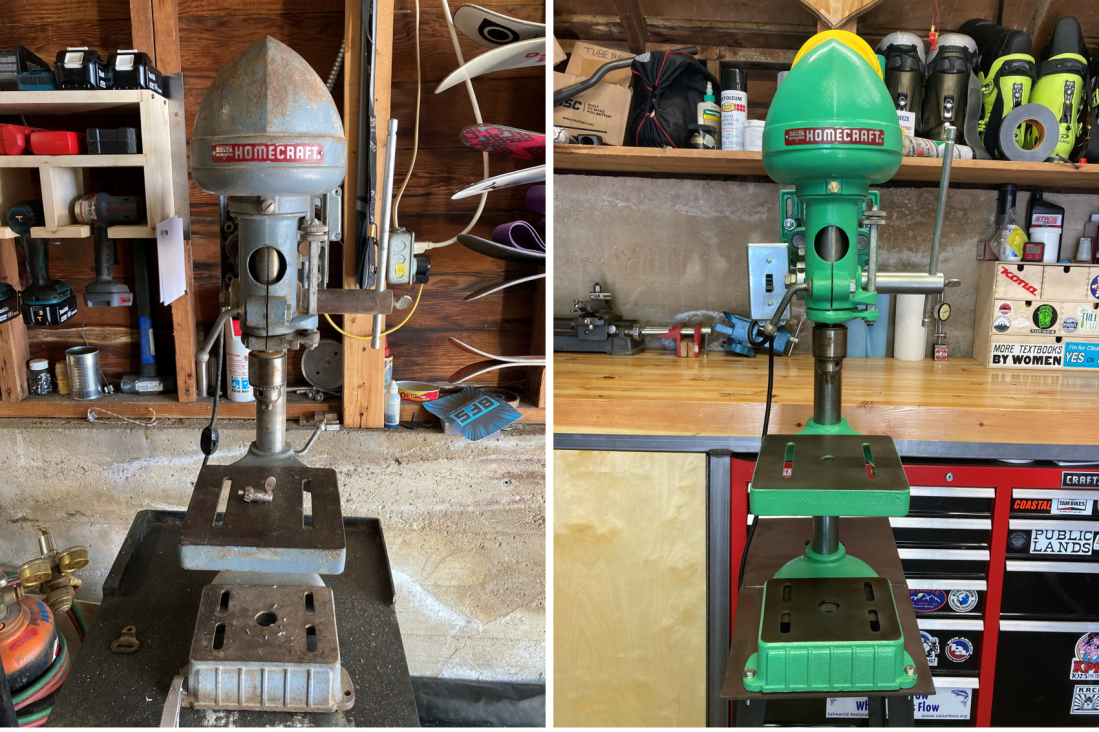
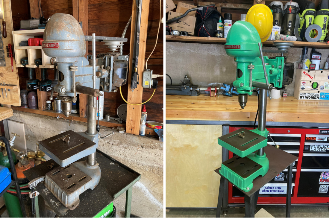
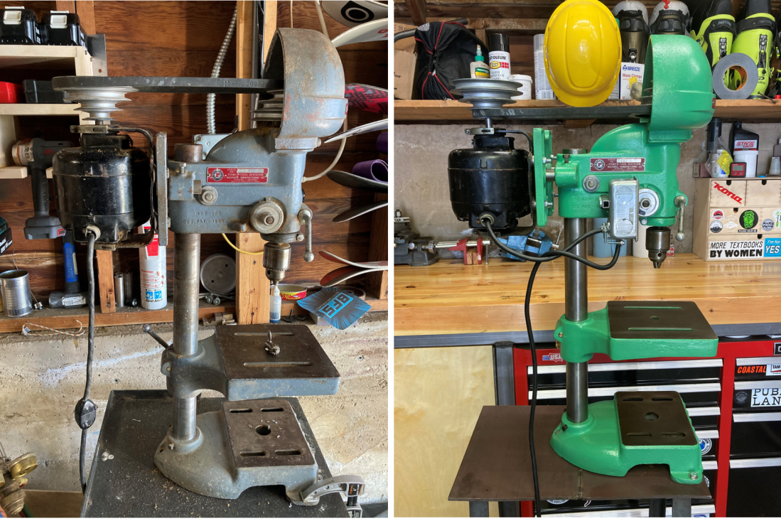


Nice! Love the color!